Method for cooling power transformer and cooling device

A technology of power transformer and cooling method, which is applied in the direction of transformer/inductor cooling, etc., which can solve the problems of large water consumption, stop production and cleaning, and high operating cost, and achieve the effect of eliminating power accidents

Inactive Publication Date: 2006-04-19
陈立人
View PDF0 Cites 3 Cited by
  • Summary
  • Abstract
  • Description
  • Claims
  • Application Information

AI Technical Summary

Problems solved by technology

[0004] 2. Large investment in equipment and water consumption
Splashing water from the cooling tower and the evaporation of the pool, as well as the rise of the water temperature in the pool, requires the entire pool to be

Method used


Image

  • Method for cooling power transformer and cooling device

Examples


Example Embodiment

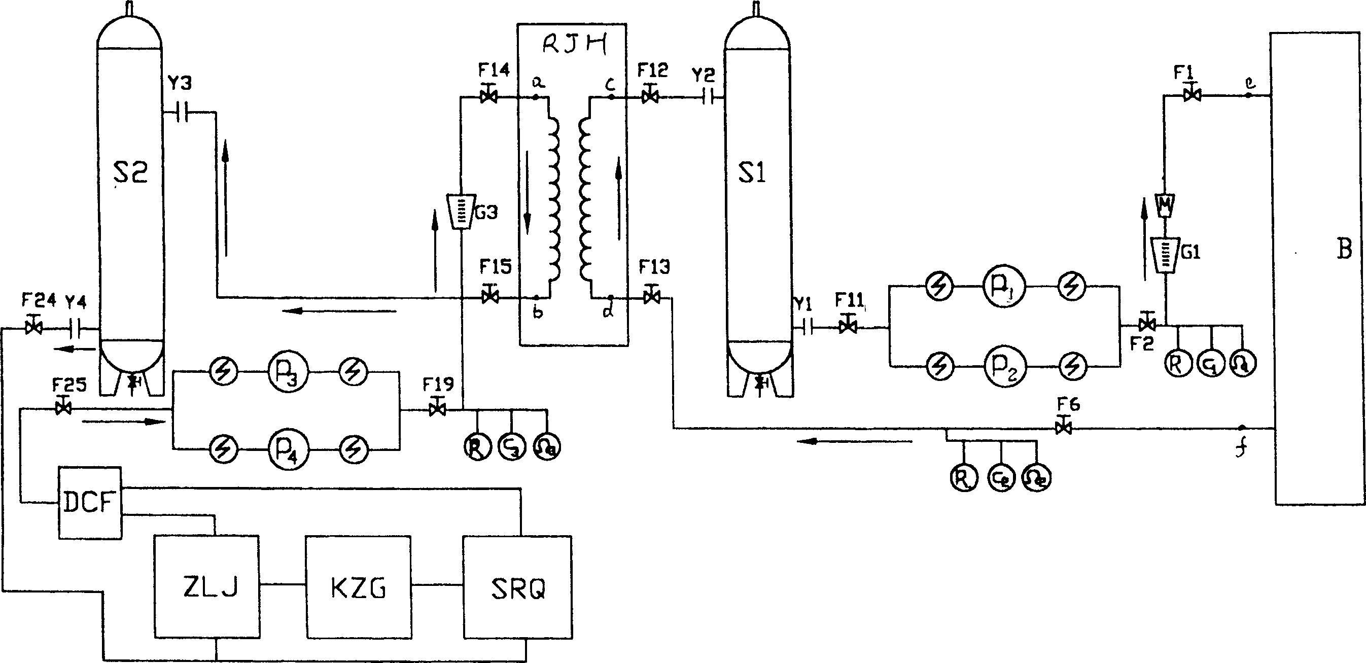
[0013] For a certain type of power transformer, it is first necessary to find out the type of transformer oil in it, or measure its quality parameters, and then select the same transformer oil or transformer oil with the same quality parameters to inject into expansion tanks S1 and S2; The two ports are connected with the oil outlet f and the oil inlet e of the transformer B, the oil pumps P1 and P3 are started, and the cooling device starts to work.

[0014] Embodiment The cooling device includes a commercially available heat exchanger RJH, in which the hot oil passage (connected in series with the closed circulation loop I) is isolated from the surrounding cold oil passage (connected in series with the closed circulation loop II). The oil inlet d of the hot end of the heat exchanger RJH is connected to the oil outlet f of the transformer B, and the oil outlet c is connected to the upper oil inlet of the low-pressure expansion tank S1, and the sensor Y2 and the valve F12 compo...


PUM


Abstract

The cooling oil in the power transformer is educed out and connected to heat exchanger so as to constitute closed loop 1. Cooling oil conspecific to the cooling oil as cooling medium of heat exchanger in the power transformer is adopted so as to constitute closed loop 2. Dedicated cooling device includes heat exchanger and expansion tanks. Through each circulating oil pump, hot end and cold end of the heat exchanger are connected to oil cooling port and cooling source. An expansion tank is cascaded in loop between cold end and cold source of heat exchanger as well as in loop between hot end and heat load respectively. The invention can prevent accident of electric power from happening effectively, and saves water resource.

Description

Technical field: [0001] The invention relates to a method and a device for cooling heat by using a heat exchanger, and is especially suitable for cooling large and medium-sized power transformers. Background technique: [0002] For traditional large and medium-sized power transformers, the transformer oil cooling system usually uses water as the medium and consists of heat exchangers, cooling towers, pools, and water pumps. Water nozzles are also used to spray the transformer shell. But these traditional water cooling systems are obviously flawed, and even cause serious safety accidents: [0003] 1. Since the oil cooling pipeline is placed in the water circuit, the water pump needs to use a high pressure to generate a large flow rate of the cooling water to quickly remove the heat of the oil pipe. Usually, the water pressure is greater than the oil pressure. If a strict mechanical isolation can be ensured between the oil pipe and the water pipe, the normal cooling operation...

Claims


Application Information

Patent Timeline
IPC IPC(8): H01F27/12H01F27/08
Inventor 陈立人
Owner 陈立人
Why Eureka
Try Eureka