
Crushing machine

A pulverizer and machine door technology, applied in grain processing, etc., can solve the problems of inability to observe and check, electric leakage, electric shock, and inability to ensure the safe use of electrical equipment, so as to prevent the machine door from loosening, feed evenly, and solve damage phenomena Effect

Inactive Publication Date: 2007-10-10
JIANGSU MUYANG GRP CO LTD
View PDF7 Cites 0 Cited by
  • Summary
  • Abstract
  • Description
  • Claims
  • Application Information

AI Technical Summary

Problems solved by technology

Since the vibration source vibration motor is located at the bottom of the closed screen frame and in the passage of the finished product, it is impossible to observe and check the vibration machine when it is working, and it cannot ensure the safe use of electrical equipment, which is prone to accidents such as leakage, electric shock, and fire.

Method used


Image

  • Crushing machine
  • Crushing machine
  • Crushing machine

Examples


Embodiment Construction

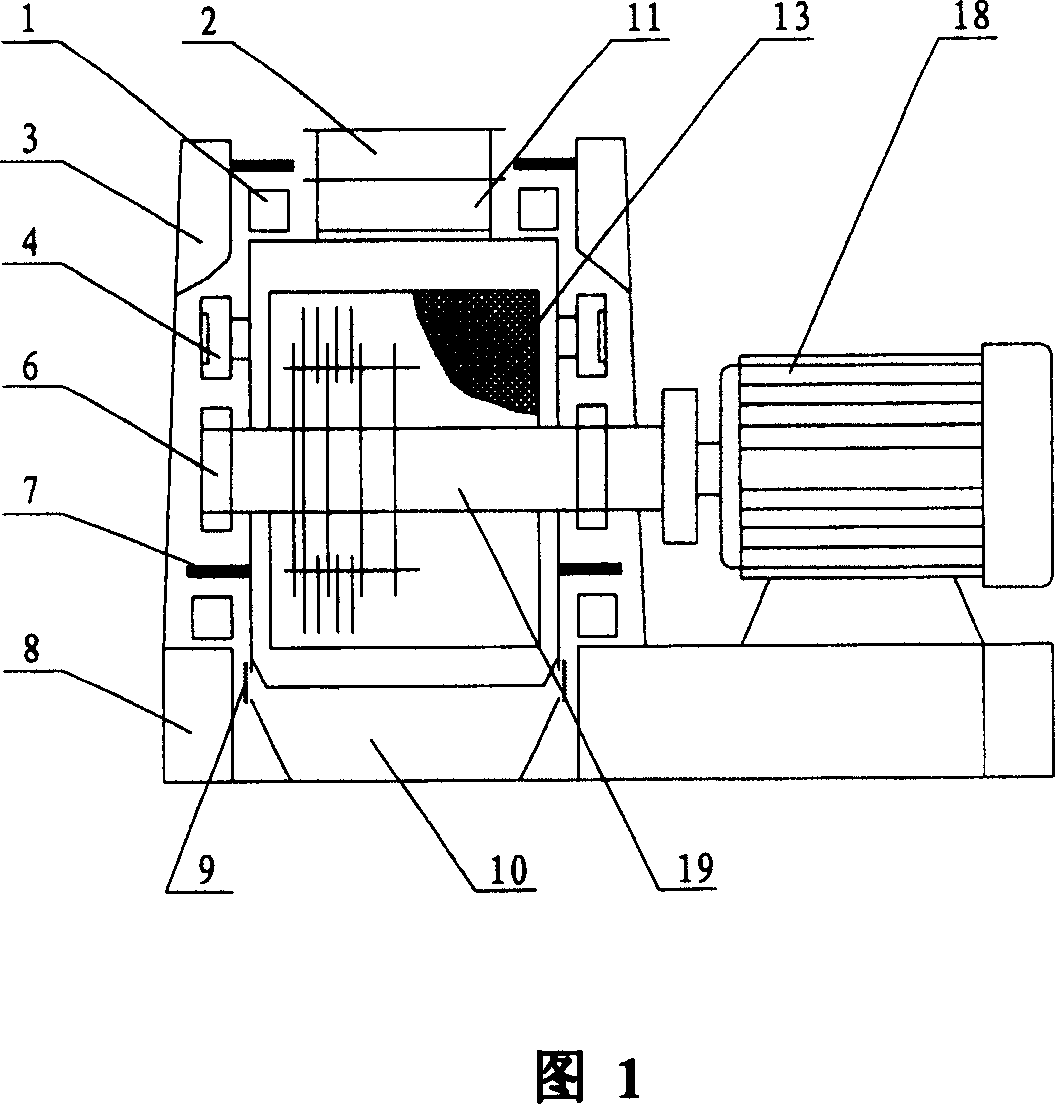
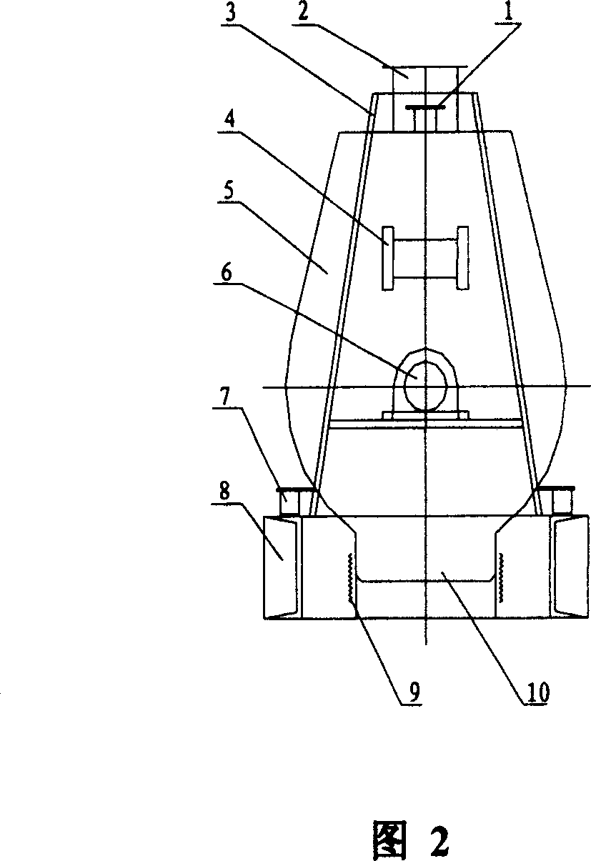
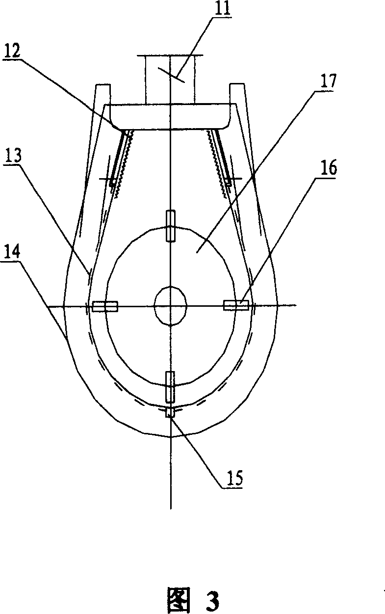
[0013] As shown in Fig. 1, 2, 3: pulverizer of the present invention comprises: main shaft 19, rotor 17, hammer blade 16, drive main shaft 19 by motor 18, make hammer blade 16 rotate at high speed and generate centrifugal force, material passes through channel to plate 11, The material inlet 2 enters the crushing room, and the qualified products are discharged through the impact of the hammer 16 and the screening of the sieve, and the materials are discharged through the outlet 10, and the unqualified materials remain in the machine to continue crushing.

[0014] Tooth plate 12, sieve piece 13, machine door 14, sieve piece bar 15, feed port 2, discharge port 10, and seal 9 are combined to form an assembly 5, and the sieve piece 13 and machine door 14 pass through the chain circumference Fasten the combination. As shown in Figure 4: the assembly 5 is rotatably connected to an upper connecting plate union buckle 20, and the other end of the upper connecting plate union buckle is...


PUM


Abstract

A pulverizer without pollution and noise is composed of mainshaft, rotor, hammer plates, feeding inlet, discharging outlet, sieving plate, base, supporting frame, vibrators, seated vibration damper between base and the assemblage consisting of toothed plate, sieving plate, gate and said inlet and outlet, and the pressing vibration damper between supporting frame and assemblage.

Description

technical field [0001] The invention relates to a shredder. Background technique [0002] In the production process of feed, food, chemical industry, medicine, fertilizer and other industries, the pulverizer is the main equipment. The common pulverizer has a motor to drive the main shaft, and the main shaft is equipped with a hammer, which hits the material during high-speed rotation. Screening achieves the purpose of crushing. [0003] The patent document of the patent No. L97234455.1 discloses a kind of hammer mill, and it uses the metal spring as the suspended isolation between the screen frame and the machine body. The bottom of the screen frame uses a shared vibration motor as the vibration source of the screen frame. The main shaft and the shaft of the vibration machine are designed in the same direction and rotate positively and negatively. Due to the function of the vibrating motor and the spring, the vibration amplitude when starting and stopping is greater than ...

Claims


Application Information

Patent Timeline
Patent Type & Authority Patents(China)
IPC IPC(8): B02C13/26B02C13/02
Inventor 樊静贤
Owner JIANGSU MUYANG GRP CO LTD
Learn More