System for transmitting data frame of Etheent based on insertion between frames

A technology of transmission system and Ethernet, which is applied in the direction of digital transmission system, transmission system, data exchange network, etc., and can solve the problems of inverse multiplexer not working normally, delay difference limitation, etc.

Inactive Publication Date: 2006-04-19
TSINGHUA UNIV
View PDF0 Cites 6 Cited by
  • Summary
  • Abstract
  • Description
  • Claims
  • Application Information

AI Technical Summary

Problems solved by technology

Since the transmission delay of each E1 channel is different, the time for each part of the same Ethernet data frame to reach the E1 receiving end is also different. The E1 receiving end must cache enough E1 frames to eliminate the delay difference of each channel before it can correctly restore all data frames. The Ethernet data frame sent, so there is a strict limit on the delay difference between the E1 lines, once it exceeds the tolerance range of the design, it will cause the inverse multiplexer to fail to work normally

Method used


Image

  • System for transmitting data frame of Etheent based on insertion between frames
  • System for transmitting data frame of Etheent based on insertion between frames
  • System for transmitting data frame of Etheent based on insertion between frames

Examples


Embodiment Construction

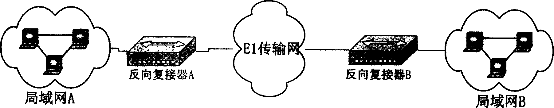
[0030] figure 1 It is the typical application environment of the Ethernet inverse multiplexer. The medium-independent interface signal of local area network A is converted into N-channel E1 signals through inverse multiplexer A, and enters the E1 transmission network of telecommunications for transmission. At the far end, the inverse multiplexer B restores the received N-channel E1 signals into Ethernet media-independent interface signals and forwards them to the local area network B, thereby realizing the communication between the two remote Ethernets.

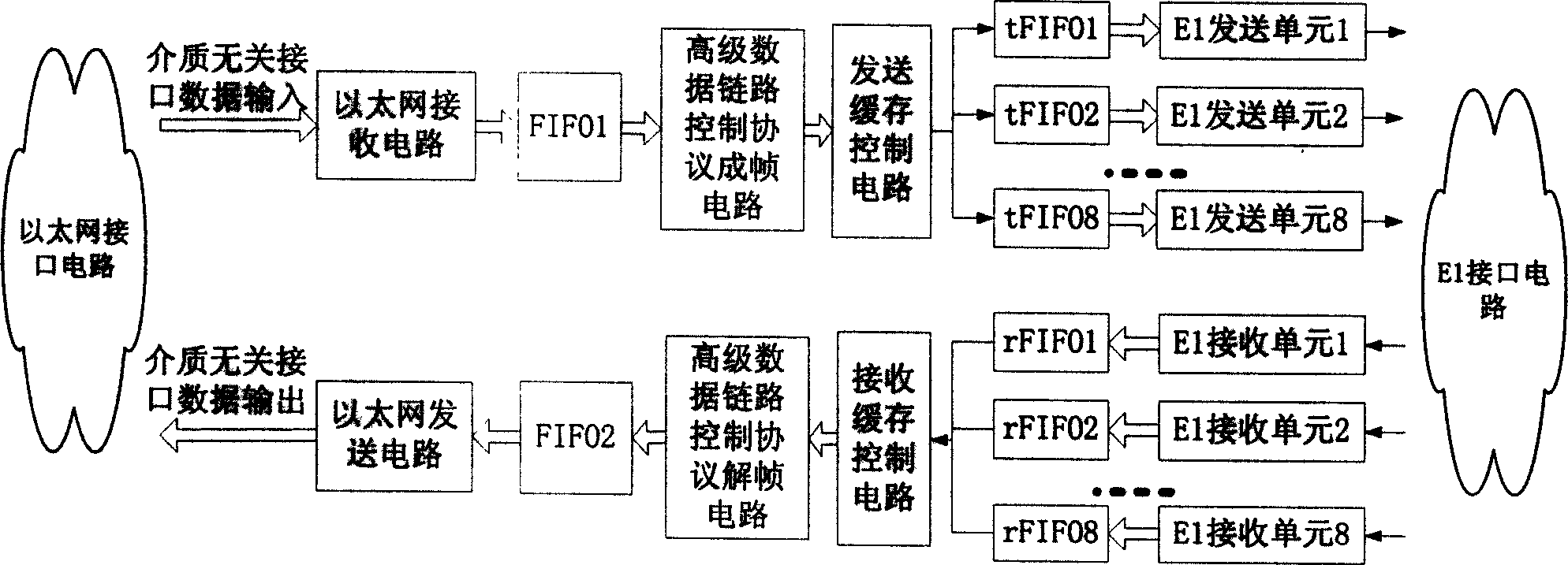
[0031] figure 2 It is the overall block diagram of the Ethernet data frame transmission system. The functions of each part of the circuit are explained one by one according to the direction of the data flow. Among them, the circuit modules (1) to (6) realize the mapping process from Ethernet to E1, and the circuit modules (7) to (12) realize the process from E1 Mapping process to Ethernet:

[0032] (1) Ethernet receiving...


PUM


Abstract

In sending direction, medium independent interface data of LAN A are input to following cascaded parts: Ethernet receiving circuit, FIFO1ú¼framing circuit in protocol of high level data link control (HDLC), sending buffer control circuit, E1 sending buffer, E1 sending circuit, and interface circuit of E1 line. In receiving direction, input signal of interface circuit of E1 line passes through following cascaded parts: E1 receiving circuit, E1 receiving buffer, receiving buffer control circuit, de-framing circuit in protocol of HDLC, FIFO2, sending circuit of Ethernet, then through medium independent interface, data inputted to LAN B. in the system, after Ethernet data frame reaches, each E1 line is polled in sequence. One integrated data frame is transferred in sequence through free line pulled from each route. The invention can eliminate issue of different time delay when one split Ethernet data frame is transferred through multiple routes of E1 line together.

Description

technical field [0001] The invention is applied to the field of electrical communication, and is an economical and effective method for connecting remote Ethernet. Background technique [0002] In the field of local area network, after years of competition of survival of the fittest, simple and economical Ethernet has become the most widely used technology. It is an inevitable trend of network development to interconnect these scattered Ethernet networks to realize a wider range of resource sharing. The Ethernet to multi-channel E1 reverse multiplexer makes full use of abundant E1 resources and is an economical and effective solution for connecting two remote Ethernet networks. [0003] The current Ethernet to multi-channel E1 inverse multiplexer on the market splits the Ethernet data frame and then transmits it. The E1 sender splits the Ethernet data frame and distributes it to each E1 for transmission. Due to the different transmission delays of each E1, the time for ea...

Claims


Application Information

Patent Timeline
Patent Type & Authority Applications(China)
IPC IPC(8): H04L12/56H04L12/46H04L29/06H04L12/861
Inventor 曾烈光金德鹏陈文涛
Owner TSINGHUA UNIV
Why Eureka
Try Eureka