Near-end crosstalk compensation at multi-stages

A technology of crosstalk and substrate, applied in coupling devices, printed circuit components, two-component connection devices, etc., can solve the problems of low frequency tolerance deterioration and high frequency tolerance deterioration.

Active Publication Date: 2006-04-19
COMMSCOPE SOLUTIONS PROPERTIES
View PDF3 Cites 2 Cited by
  • Summary
  • Abstract
  • Description
  • Claims
  • Application Information

AI Technical Summary

Problems solved by technology

[0007] Thus, while low frequency tolerance (low frequency characteristics of the connector) can be improved by increasing the level of compensation when high crosstalk plugs are used in jacks, this behavior causes further deterioration in high frequency tolerance when low crossta...

Method used


Image

  • Near-end crosstalk compensation at multi-stages
  • Near-end crosstalk compensation at multi-stages
  • Near-end crosstalk compensation at multi-stages

Examples


Embodiment Construction

[0019] The examples shown in the drawings will now be described in detail with reference to the preferred embodiments of the present invention. In this application, "level" refers to the location where the compensation occurs at the compensation delay point.

[0020] The present invention provides printed circuit boards (PCBs) of various configurations that can replace the printed circuit board of Figure 7A of the '358 patent. In some embodiments, the PCB of the present invention is constructed by laminating a plurality of substrates with different dielectric constants (DK).

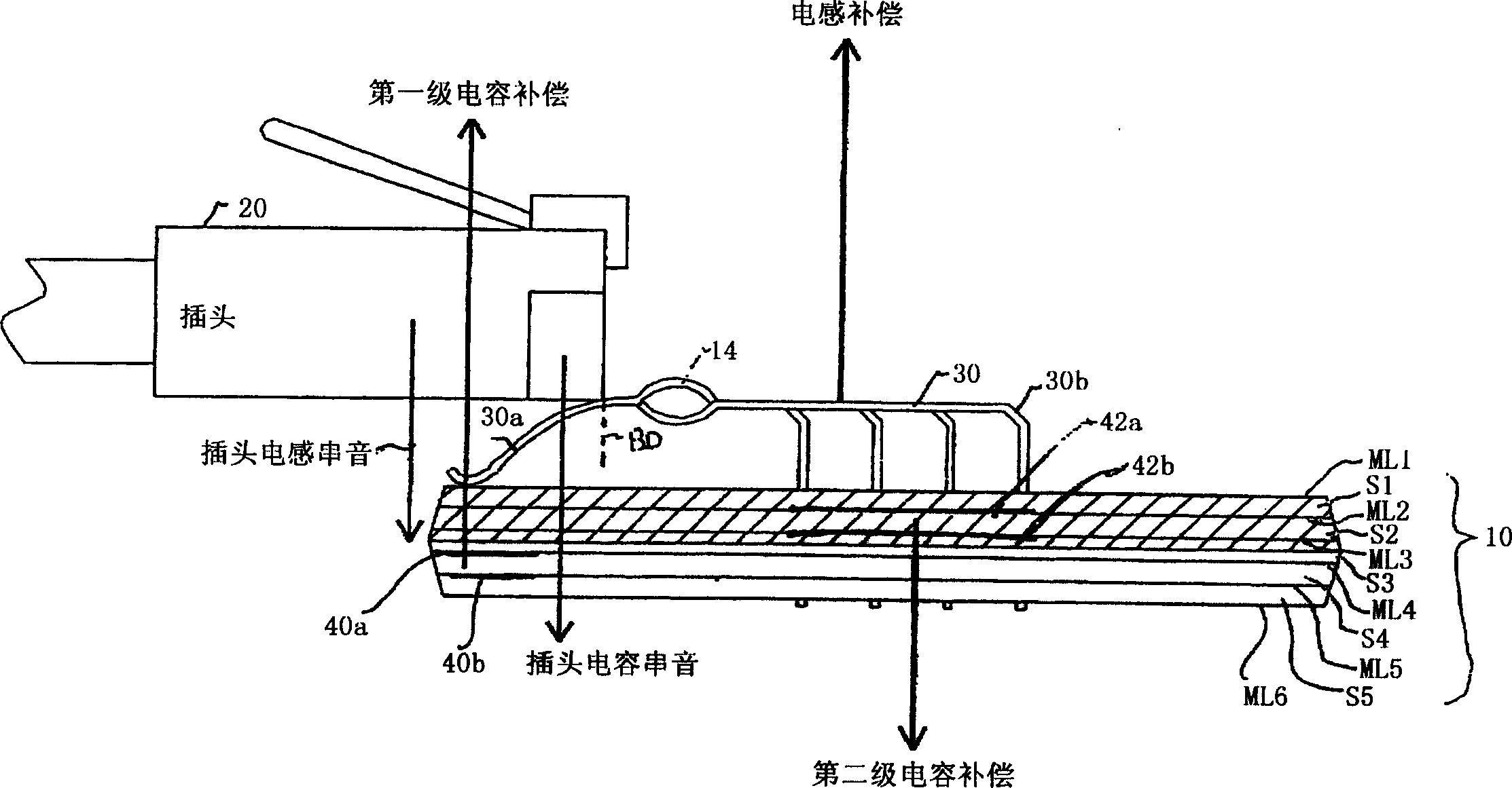
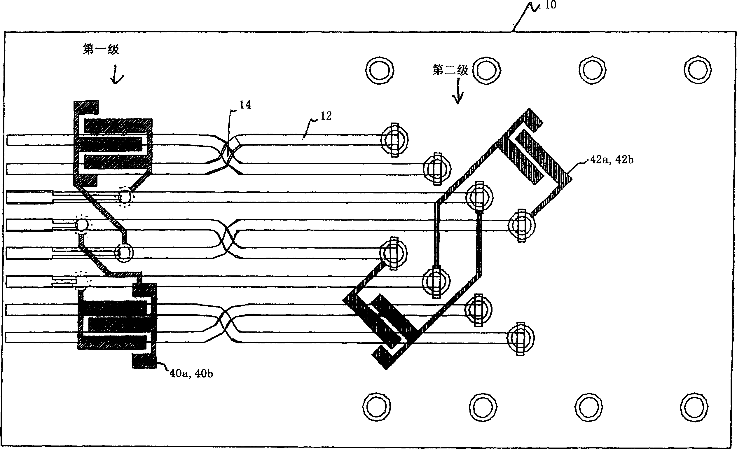
[0021] According to the first embodiment of the present invention, FIG. 1( a ) is a side view of the connector, and FIG. 1( b ) is a top plan view of the printed circuit board and compensation capacitor of FIG. 1( a ).

[0022] refer to Figure 1(a) with 1(b) , the connector includes contacts 30 with jumpers 14 and a hybrid PCB 10 where the plug 20 is mated with the connector. Plug 20 may be a modula...


PUM


Abstract

A connector is provided for simultaneously improving both the NEXT high frequency performance when low crosstalk plugs are used and the NEXT low frequency performance when high crosstalk plugs are used. The connector includes PCB substrates made of materials having different dielectric frequency characteristics.

Description

[0001] This application claims priority to US Provisional Application No. 60 / 456,236, filed March 21, 2003, the entire contents of which are incorporated herein by reference. technical field [0002] The present invention relates to near-end crosstalk (NEXT) compensation in communication connectors, and more particularly to techniques for eliminating or reducing NEXT using substrates such as printed circuit boards (PCBs) composed of different dielectric constant materials. Background technique [0003] Noise or signal interference between conductors in a connector is known as crosstalk. Crosstalk is a common problem in communication devices using connectors. In particular, in communication systems where an analog-to-digital plug, often used in computers, mates closely with an analog-to-digital jack, the conductive wires (conductors) inside the jack and / or plug cause near-end crosstalk (NEXT), i.e., in short distance...

Claims


Application Information

Patent Timeline
IPC IPC(8): H05K1/02H01R24/00
Inventor 鲁克·阿德里思阿米德·哈西姆特洛伊·朗
Owner COMMSCOPE SOLUTIONS PROPERTIES
Why Eureka
Try Eureka