

Device for monitoring the position and displacement of a brake pedal.
A technology of brakes and pedals, applied in the direction of hydraulic brake transmissions, brakes, etc., can solve the problems of multiple brake light switches and complicated brake light switches
- Summary
- Abstract
- Description
- Claims
- Application Information
AI Technical Summary
Problems solved by technology
Method used
Image

Examples
Embodiment Construction
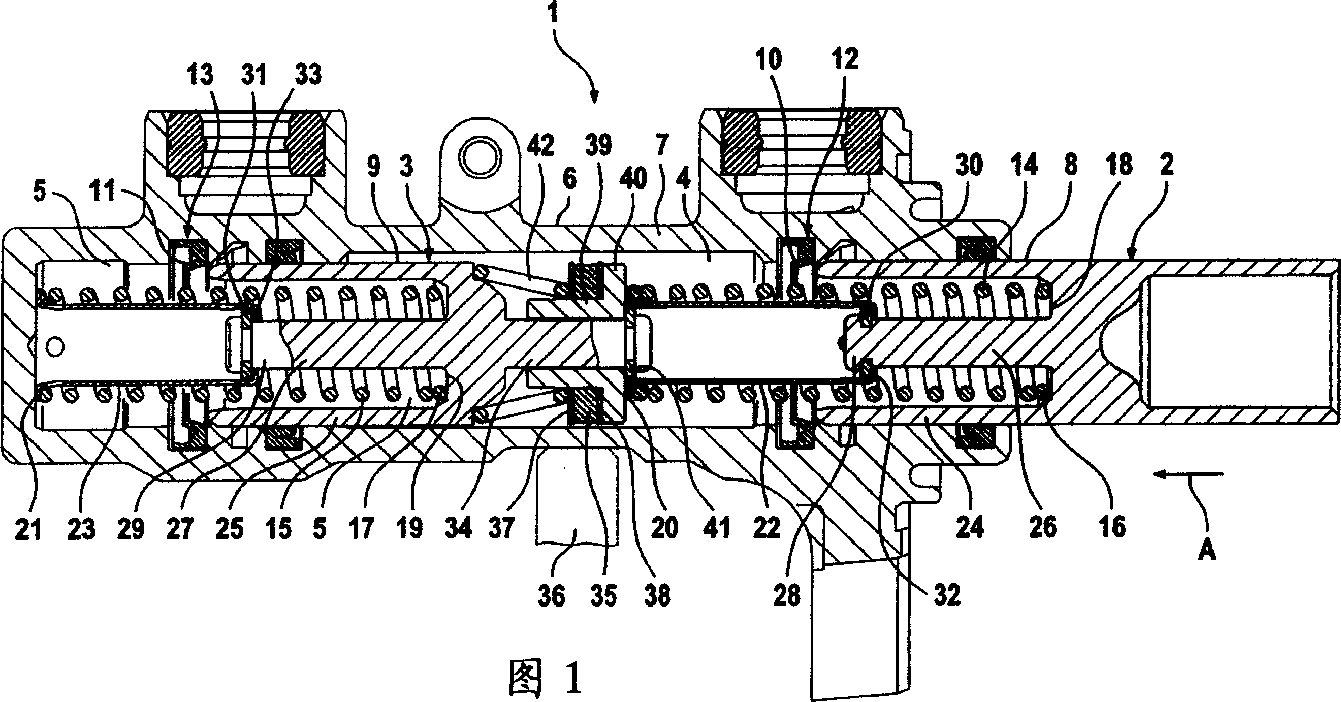
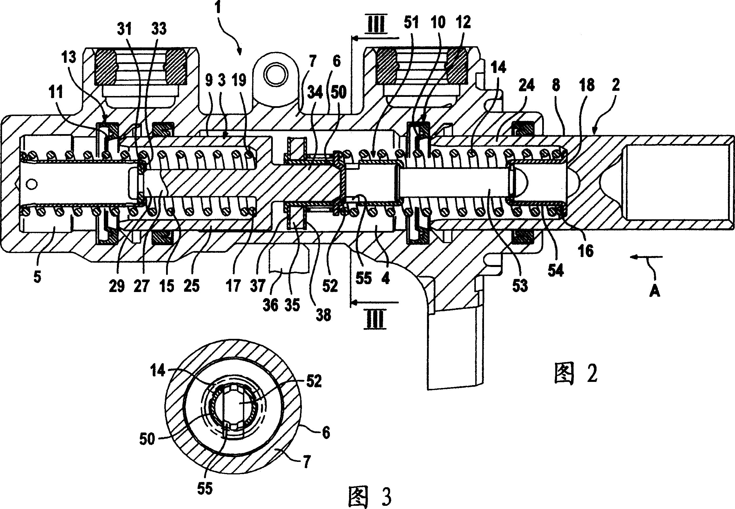
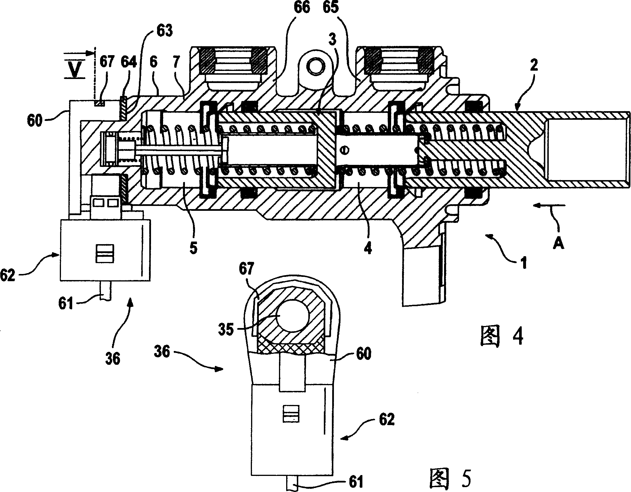
[0029] The vehicle brake system comprises, in addition to the wheel brakes, valves (inlet valves, outlet valves, separation valves and switchover valves) which are connected to the wheel brakes by means of pipes and hose lines (inlet valves, outlet valves, separation valves and switching valves to create a change in the suction line of the pump to generate pressure in at least one wheel brake) hydraulic unit with integrated return pump or pressure boost pump and pedal-operable master cylinder 1, said master The cylinder has first and second pistons 2, 3 for first and second pressure chambers 4, 5, wherein the pistons 2, 3 are movably arranged inside the housing 6 to be contained in pairs in the brake The wheel brakes in the circuit supply the pressure medium. It is understood that a brake booster for generating the servo force can be arranged upstream of the master cylinder 1 , although in principle this can also be achieved by other sources of pressure increase, for example a...
PUM
 Abstract
Description
Claims
Application Information