Upright type photocatalytic air sterilizing purifying device

An air sterilization and purification device technology, applied in the field of air purification, to achieve the effect of reasonable design, high efficiency and improved function

Inactive Publication Date: 2006-05-10
SHAANXI NORMAL UNIV
View PDF2 Cites 14 Cited by
  • Summary
  • Abstract
  • Description
  • Claims
  • Application Information

AI Technical Summary

Problems solved by technology

[0005] The technical problem to be solved by the present invention is to overcome the shortcomings of the above-mentioned indoor air purification products and patents, and provide a vertical photocatalytic air purification system with reasonable design, simple structure, fast purification speed, high efficiency, no secondary pollution, and fresh air. Sterilization and purification device

Method used


Image

  • Upright type photocatalytic air sterilizing purifying device
  • Upright type photocatalytic air sterilizing purifying device

Examples


Embodiment 1

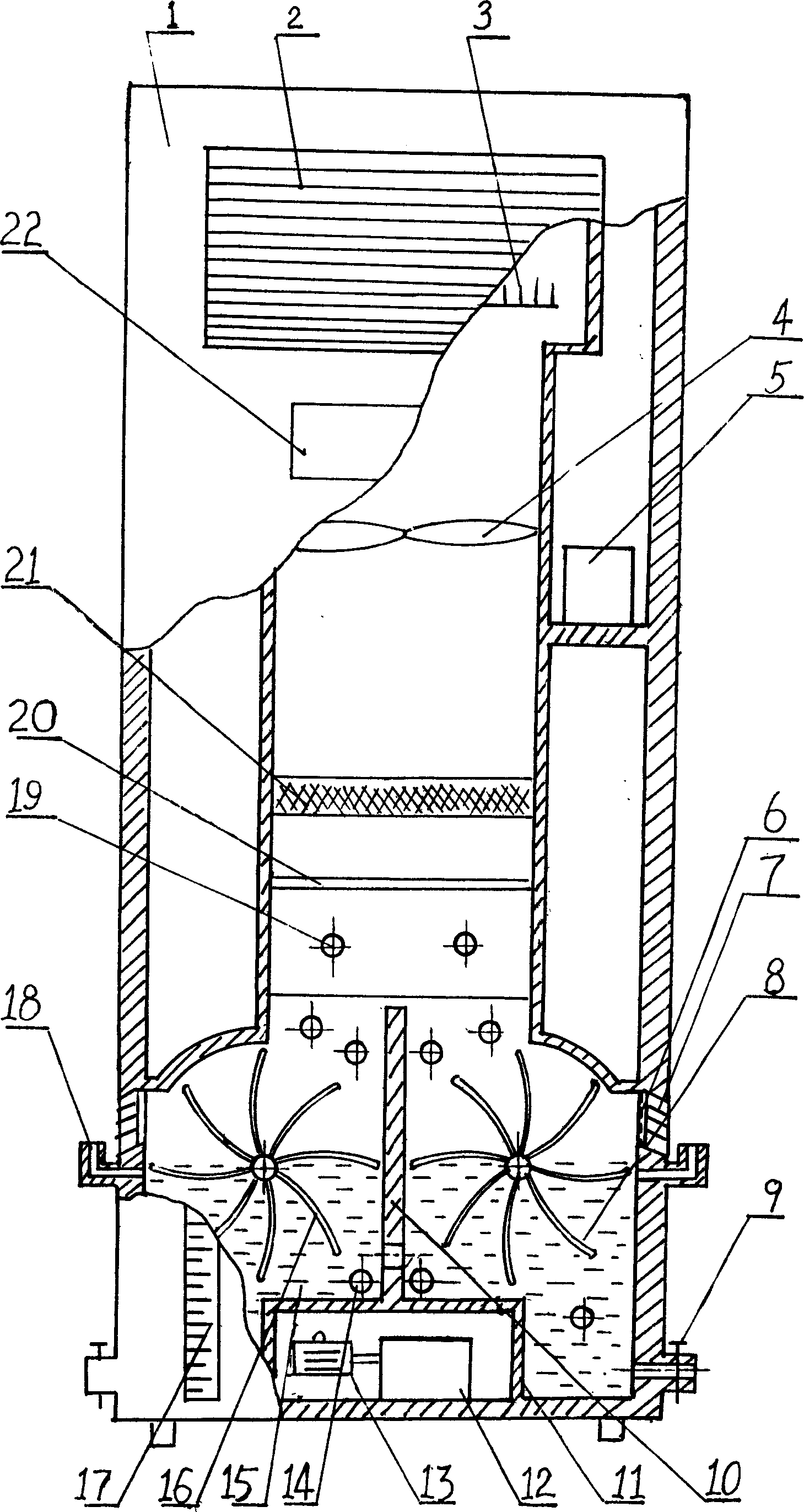
[0018] exist figure 1 , 2 Among them, the vertical photocatalytic air sterilization and purification device of the present embodiment is composed of a housing 1, an air outlet louver 2, an anion generator 3, an axial flow fan 4, an anion generator power supply 5, an air inlet filtering net 6, and an air inlet louver 7. Right photocatalytic wind wheel 8, purification liquid discharge valve 9, purification room partition 10, power chamber 11, gear box 12, speed regulating motor 13, purification liquid ultraviolet lamp 14, purification liquid 15, left photocatalytic wind Wheel 16, liquid level scale 17, purification liquid filling valve 18, ultraviolet lamp 19, photocatalytic net 20, activated carbon filter screen 21, control panel 22 are connected to form.

[0019] A power chamber 11 and a clean room partition 10 are cast-molded at the lower part of the rear side in the housing 1. The clean room partition 10 divides the lower part of the housing 1 into a left clean room and a r...

Embodiment 2

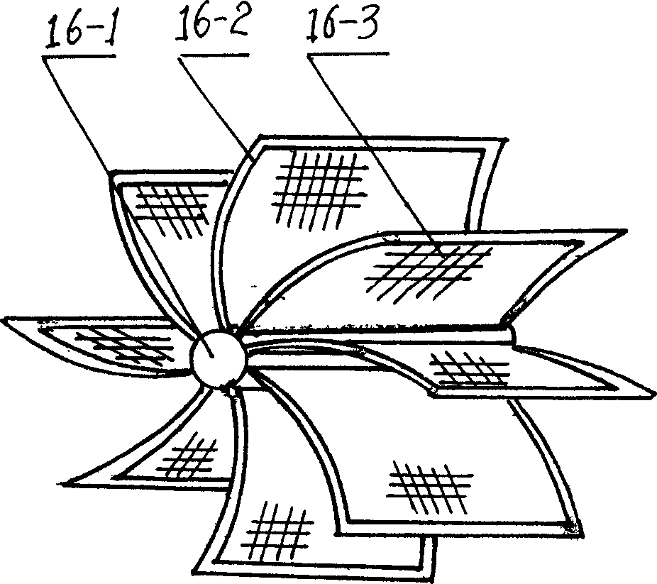
[0024] In the present embodiment, the photocatalytic net 20 is a 40-mesh surface coated with anatase nano-TiO 2 stainless steel mesh. The left photocatalytic wind wheel 16 is fixed and fixed with six skeletons 16-2 in the radial direction of the rotating shaft 16-1 with threaded fastening joints, and a wind wheel photocatalytic net is fixedly installed on each skeleton 16-2 16-3, the skeleton 16-2 and the wind rotor photocatalytic net 16-3 constitute the wind rotor blade of the left photocatalytic wind rotor 16, and the wind rotor photocatalytic net 16-3 is nano-TiO coated with anatase crystal on the surface of 40 mesh 2 stainless steel mesh. The right photocatalytic wind wheel 8 has the same structure as the left photocatalytic wind wheel 16, and the bending direction of the right photocatalytic wind wheel 8 is opposite to that of the left photocatalytic wind wheel 16. Purifying liquid 15 is housed at the bottom in housing 1, and purifying liquid 15 is made of H 2 o 2 and...

Embodiment 3

[0026] In the present embodiment, the photocatalytic net 20 is coated with anatase nano-TiO on the surface of 50 mesh. 2 stainless steel mesh. The left photocatalytic wind wheel 16 is fixed and fixed with 12 skeletons 16-2 in the radial direction of the rotating shaft 16-1 with threaded fastening joints, and a wind wheel photocatalytic net is fixedly installed on each skeleton 16-2 16-3, the skeleton 16-2 and the wind rotor photocatalytic net 16-3 constitute the wind rotor blade of the left photocatalytic wind rotor 16, and the wind rotor photocatalytic net 16-3 is nano-TiO coated with anatase crystal on the surface of 50 mesh 2 stainless steel mesh. The right photocatalytic wind wheel 8 has the same structure as the left photocatalytic wind wheel 16, and the bending direction of the right photocatalytic wind wheel 8 is opposite to that of the left photocatalytic wind wheel 16. Purifying liquid 15 is housed at the bottom in housing 1, and purifying liquid 15 is made of H 2 ...


PUM

PropertyMeasurementUnit
wavelengthaaaaaaaaaa

Abstract

The invention relates to a vertical photo-catalysis air disinfection purifying device. In the lower part of casing, it arranges a adjustable speed motor and connected power room, a ultraviolet lamp, and a photo-catalysis of change-speed gear box; one photo-catalysis wind-wheel, a fluid level gage, purifying liquid and purifying liquid ultraviolet lamp in the purifying liquid, while at least one of them is connected to the change-speed gear box. In the middle part of casing, it arranges an axial flown fan and an active carbon screen. In the upper part of casing, it arranges a negative-ion generator connected to its power source via lead wire, a control panel and an outlet shutter. At the side surface of lower part of casing, it arranges an inlet screen, an inlet shutter, a purifying liquid feeding valve, and a purifying liquid discharging valve. The invention has reasonable design, simple structure, fast purifying speed, high efficiency while it can refresh air without secondary pollution, and it can be used in hospital, classroom, cinema and house etc.

Description

technical field [0001] The invention belongs to the technical field of air purification, and in particular relates to a vertical photocatalytic air sterilization and purification device. technical background [0002] The hazards of indoor air pollution to human health are well known, especially the impact on children and the elderly and the sick. Scientists pointed out that while human beings are enjoying the material civilization brought about by industrial development, they are facing the accompanying hazards. After experiencing soot-type pollution and photochemical smog-type pollution, human beings have entered the period of indoor pollution. But people did not stop because of the negative effects of home decoration, which prompted the rapid development of the air purification industry. [0003] There are many indoor air purification products sold on the market at present, and hundreds of patent applications have been submitted to the Chinese Patent Office. The structu...

Claims


Application Information

Patent Timeline
Patent Type & Authority Applications(China)
IPC IPC(8): A61L9/20B01D53/78B01J19/12
Inventor 张宗权
Owner SHAANXI NORMAL UNIV
Why Eureka
Try Eureka