

Ultrasonic receiver transmitter
A technology for receiving transmitters and ultrasonic waves, which is applied in the directions of sound wave re-radiation, instruments, sensors, etc., can solve the problems such as the decrease of reflection sensitivity, and achieve the effect of small change in electrostatic capacity and high reflection sensitivity
- Summary
- Abstract
- Description
- Claims
- Application Information
AI Technical Summary
Problems solved by technology
Method used
Image

Examples
Embodiment
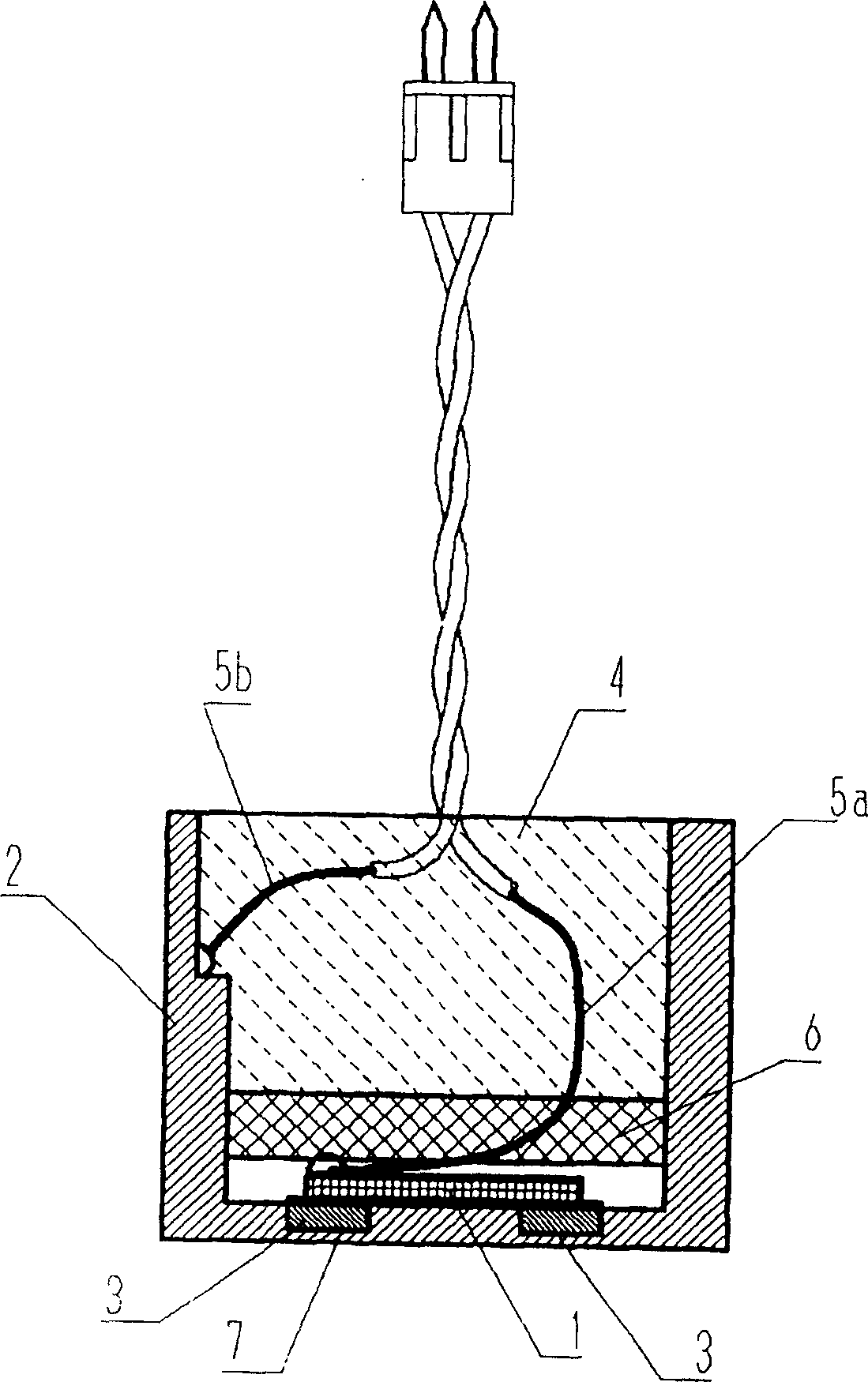
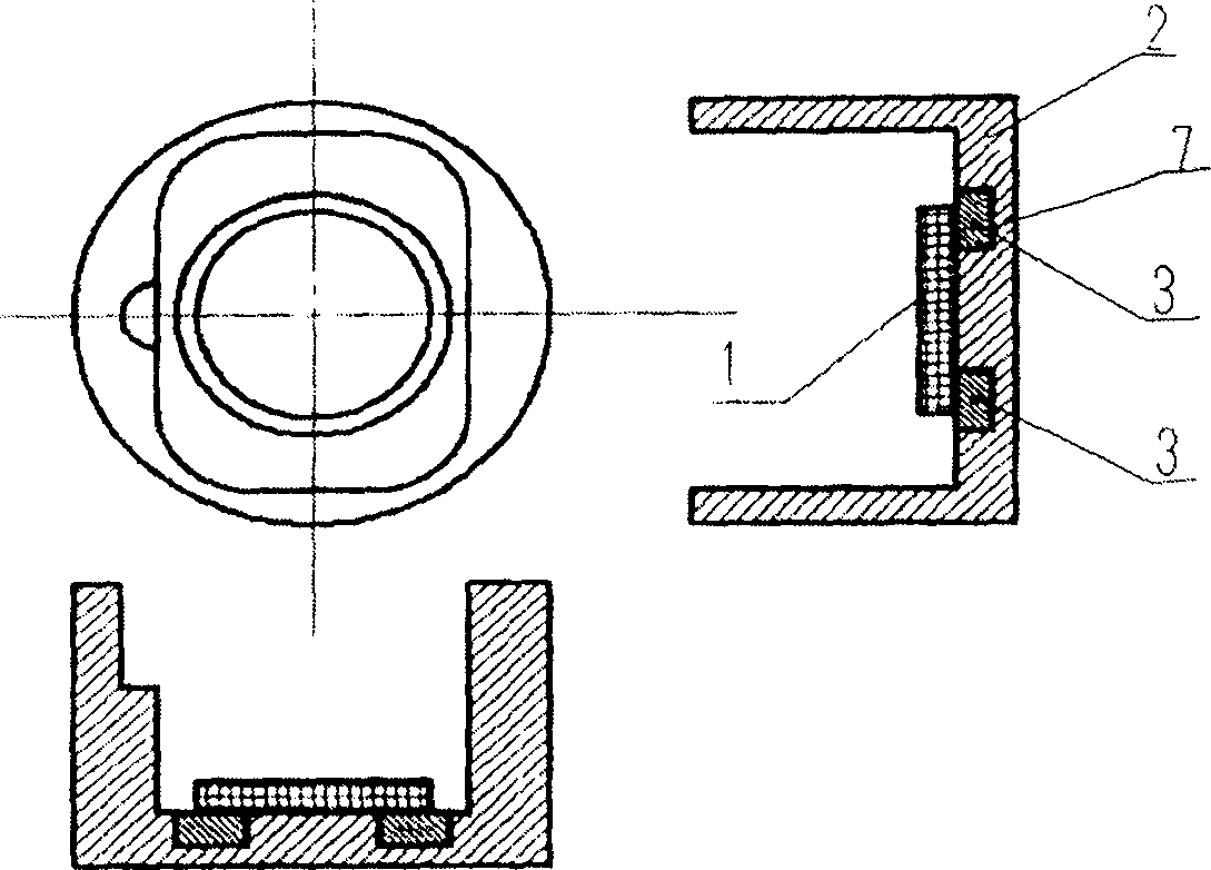
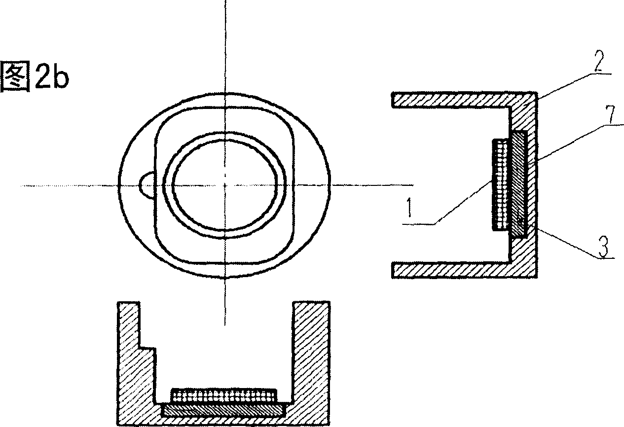
[0030] figure 1 A schematic longitudinal sectional view showing an ultrasonic transceiver according to an embodiment of the present invention. Fig. 2 (a) is a schematic plan view and a longitudinal sectional view of a bottomed cylindrical housing of an ultrasonic transceiver of an embodiment of the present invention, and Fig. 2 (b) and Fig. 2 (c) show another embodiment of the present invention The schematic top view and longitudinal sectional view of the bottomed cylindrical shell of the ultrasonic transmitter and receiver. figure 1 Among them, an annular groove 7 is provided inside the bottom surface of a bottomed cylindrical shell 2 made of aluminum material, etc., and a plate 3 made of the same annular low thermal expansion alloy or the like is embedded into the device by bonding or press-fitting. In the groove 7 of the bottomed cylindrical case, the piezoelectric element 1 is pasted on it to form a single-plane waviness vibrator. In addition, the groove 7 provided in th...
PUM
 Abstract
Description
Claims
Application Information