Determination of center of focus by parameter variability analysis

A variable and parametric technology, applied in the direction of using optical devices, printing devices, instruments, etc.

Inactive Publication Date: 2006-05-10
ACCENT OPTICAL TECH
View PDF19 Cites 4 Cited by
  • Summary
  • Abstract
  • Description
  • Claims
  • Application Information

AI Technical Summary

Problems solved by technology

The Bossung plot discussed above

Method used


Image

  • Determination of center of focus by parameter variability analysis
  • Determination of center of focus by parameter variability analysis
  • Determination of center of focus by parameter variability analysis

Examples


Embodiment 1

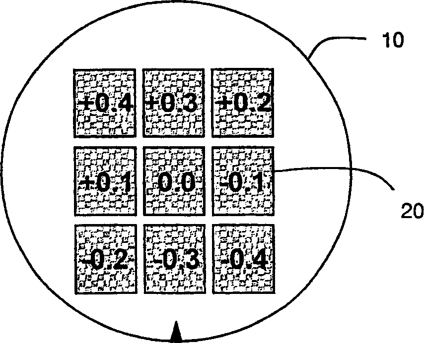
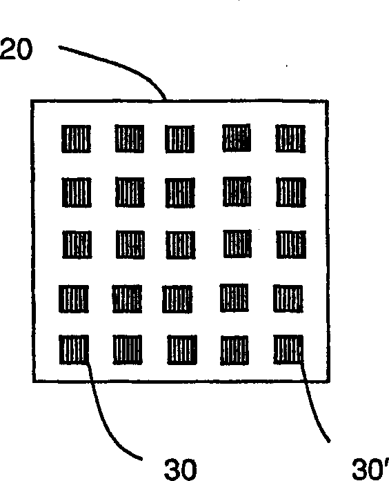
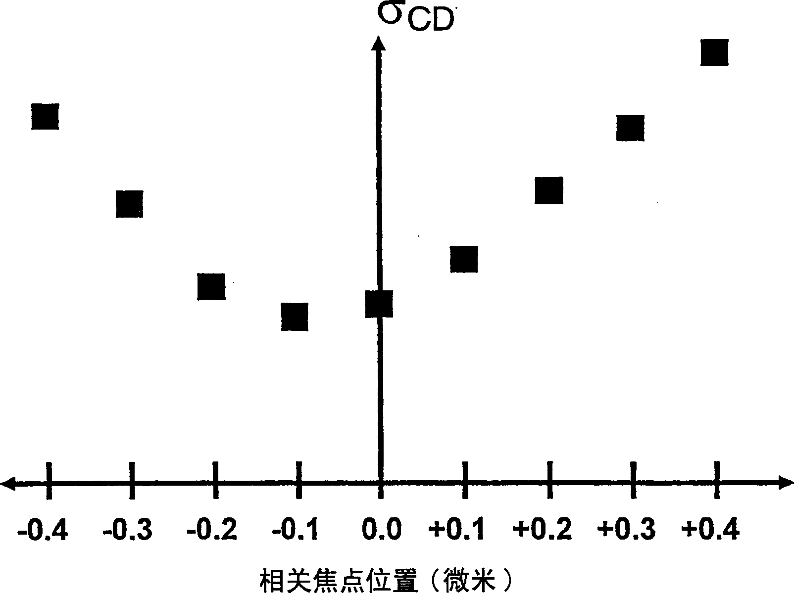
[0106] According to the present invention, five fields are exposed with different focus values ​​from -0.2 micron to +0.2 micron in increments of 0.1 micron as focal points. Each field comprises a 5x5 array of evenly spaced diffractive structures. Figures 3A-3E The CD of the diffractive structure in each field is shown graphically. Figure 4 is a graph of the 1-sigma standard deviation of the CD of all 25 diffractive structures in each field. Optimal focus was obtained at the -0.1 micron focus position as described above.

[0107] It is important for real-time focus control and process control to be able to correct for focus drift before it becomes too large. It is thus beneficial to control the CD or other selected features of a subset of diffractive structures that exhibit greater variation in selected features than the variation of all 25 diffractive structures in each field . For example, selected features of diffractive structures located in the corners of the field ...

Embodiment 2

[0110] According to the second preferred embodiment above, Figure 7 Diffractive features emerging from five separate diffractive structures within each of the three fields aimed at different focus values ​​are depicted. In this embodiment, it is readily determined by inspection that the change in properties is minimal for the field aimed at the 0.0 micron focus. Figure 7 The graph in plots the range or distribution of the characteristic strength for each field. As expected, the field aimed at 0.0 focus is the minimum, which is the field at best focus. This method can replace the above-described embodiments for all purposes, including those of process control and focus shift control.

Embodiment 3

[0112] When manufacturing multiple wafers printed with the same mask and with the same process, a typical process control application involves controlling the change timeout of selected features. Figure 8 represents the change of the selected feature measured at one-hour intervals (in this case the measured change in CD as a 3-sigma of the measured values, the center of focus is preferably pre-determined on the illuminated field according to the method of the invention ). Since the same diffractive structures in the same field are measured for each wafer, and each wafer is printed with the same mask and process, the variability should be the same from wafer to wafer. However, the focus of lithography tools can shift over time, which can lead to higher CD deviations such as Figure 8 shown. According to common knowledge, an acceptable amount of variation for process control is 2.4nm. Therefore, the control limit of 2.4nm is indicated by the dotted line at Figure 8 middle....


PUM


Abstract

A method for judging the center of focus and process control of a lithography tool. Diffractive features are obtained from multiple diffractive structures located within multiple different focus setting fields. The variability of the diffraction characteristics of each field is determined by direct analysis or comparison with a database. The variability or uniformity can be represented by any measurement, including the standard deviation or range of values ​​of selected features of a database of theoretical diffraction structures or the variability or uniformity of the diffractive features themselves, as represented by RMS differences or intensity ranges. These methods can be used to process control and monitor focus shift by determining the internal field variation of the diffractive features of multi-diffractive structures in a series of wafers.

Description

[0001] Cross References to Related Applications [0002] This application claims priority to U.S. Provisional Patent Application No. 60 / 462,353, entitled "Determination of Center of Focus In Lithographic Applications," filed April 10, 2003, which It is hereby incorporated by reference. technical field [0003] The invention relates to a method for judging parameters in lithography equipment and applications by analyzing the changes in the measured values ​​of a plurality of diffractive structures located in different fields on a wafer, including the judgment of the focus center in lithography applications, such as wafers ( photolithographic processing of photoresist on wafer), and a method of controlling processing and quality using the judgment result. Background technique [0004] Note that the discussion below is for the author's multiple publications and publications over the years, and due to recent publication dates, some publication dates are not considered to be pri...

Claims


Application Information

Patent Timeline
IPC IPC(8): G03B27/52G01B9/00G01B11/04G01B11/06G03C5/00G03F7/20
Inventor 迈克尔·E·利陶克里斯托弗·J·雷蒙德
Owner ACCENT OPTICAL TECH
Why Eureka
Try Eureka