
Negative terminal and electric connector using the same negative terminal

A female terminal and terminal technology, which is applied in the field of female terminals and electrical connectors using the female terminals, can solve the problems of difficult plugging and unplugging operations, high contact pressure, and micro-slip wear, so as to prevent micro-slip wear and prevent micro-slip Abrasion, not easy to reverse the effect

Inactive Publication Date: 2006-05-17
TYCO ELECTRONICS JAPAN GK
View PDF1 Cites 10 Cited by
  • Summary
  • Abstract
  • Description
  • Claims
  • Application Information

AI Technical Summary

Problems solved by technology

However, in the case of this type of terminal, a large insertion force is required due to the high contact pressure
Therefore, for example, when it is necessary to insert or remove a blade terminal or a female terminal in order to change the routing of the wiring, as the number of poles increases, the force required for the operation increases, the insertion and extraction work becomes difficult, and a dedicated tool is also required.
[0006] On the other hand, in the case of the latter female terminal, the force required for insertion and extraction is not large, but in the case of vibration, the contact part between the blade terminal and the female terminal may be subjected to vibration and micro-slip occurs. abrasion
If this kind of micro-sliding wear occurs, metal powder (metal shavings) will be generated. If the oxidized oxide of this metal powder is interposed between the contacts of the terminals, it will have a bad effect of increasing the resistance.
[0007] In addition, when plugging and unplugging, if the blade terminal or contact piece is deformed due to torsion, micro-sliding wear is prone to occur

Method used


Image

  • Negative terminal and electric connector using the same negative terminal
  • Negative terminal and electric connector using the same negative terminal
  • Negative terminal and electric connector using the same negative terminal

Examples


Embodiment Construction

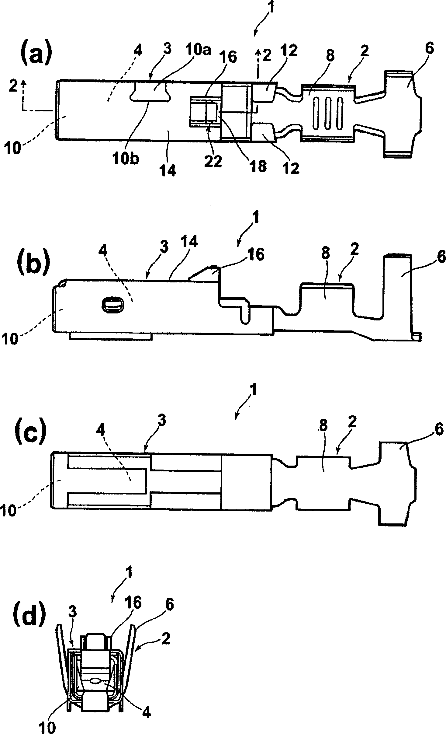
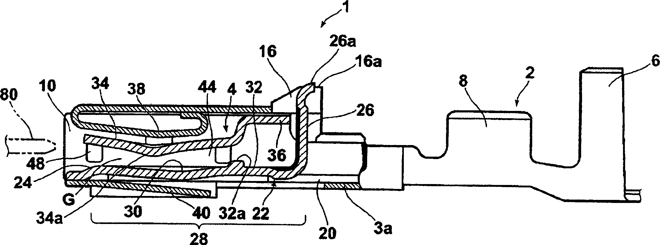
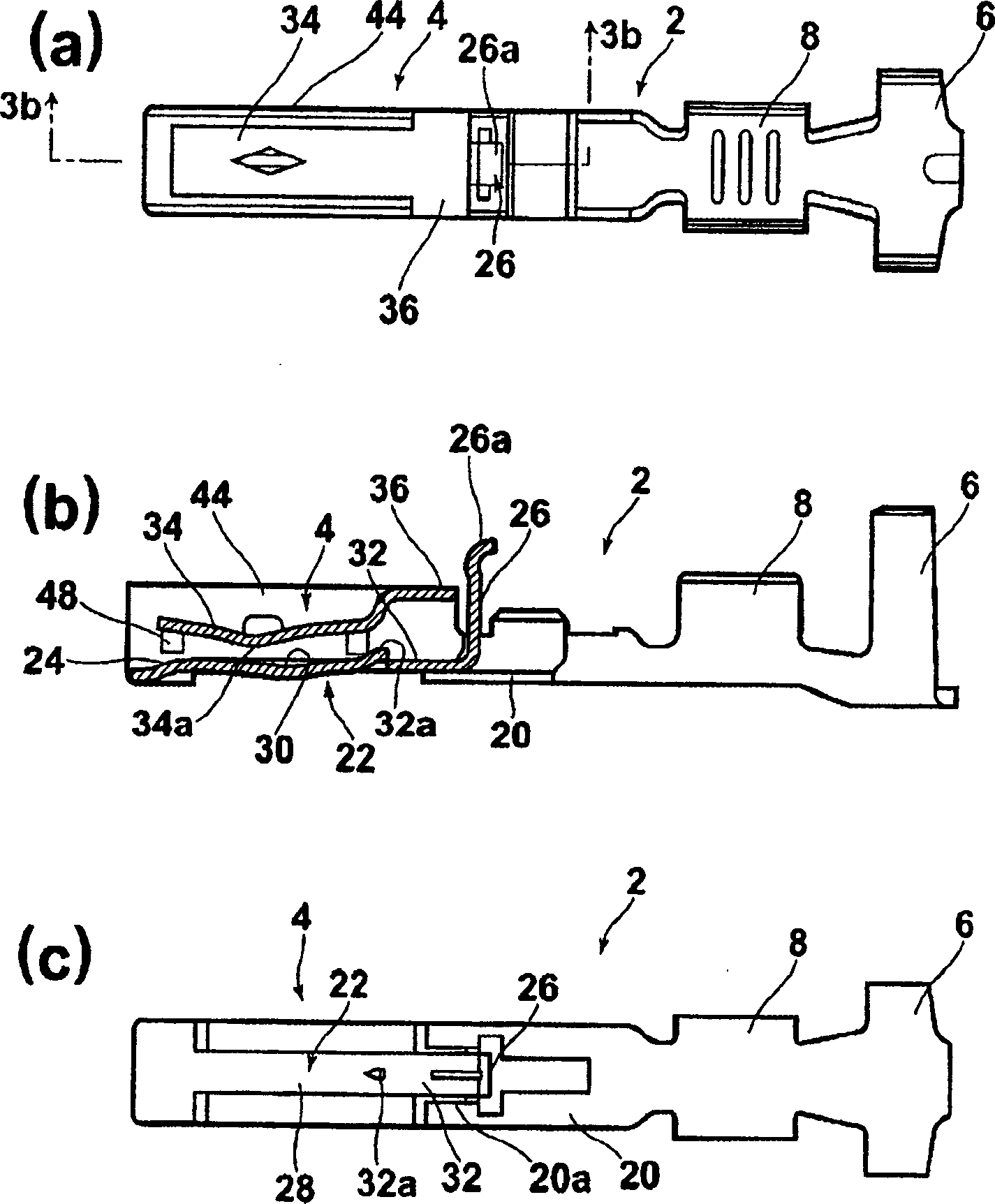
[0025] Hereinafter, preferred embodiments of the female terminal and the electrical connector of the present invention will be described with reference to the drawings. In addition, in the description, the expressions of up, down, left, and right are for the convenience of description, and refer to up, down, left, and right in the drawings. figure 1 represents the female terminal of the present invention, figure 1 (a) represents a top view, figure 1 (b) represents a side view, figure 1 (c) represents a bottom view, figure 1 (d) shows the front view. Such as figure 1 As shown, the female terminal 1 is composed of two parts: a main body (terminal main body) 2 and a reinforcement member 3 which is a cover member attached to the main body 2 . The main body 2 has a matching blade terminal 80 ( figure 2 ) connected contact portion 4 has a sheath 152 ( Figure 9 ) connected tongue-shaped insulating cylinder (barrel) (wire connection portion) 6, and a tongue-shaped condu...


PUM


Abstract

The invention provides a female terminal and an electrical connector. The female terminal is not easy to produce micro-sliding wear due to vibration, can obtain strong contact pressure, and has good workability under low insertion force. Also, prevent twisting. A female terminal (1), including two parts, a terminal body (2) and a reinforcing part (3) installed on the terminal body, the terminal body (2) has a plug-in piece that is inserted in the front The elastic contact piece (34) that the terminal (80) contacts, and has the electric wire connecting part (6, 8) that is connected with the electric wire at the back, and the described strengthening part (3) has the spring piece (38), and above-mentioned contact piece ( 34) When deflected due to contact with the above-mentioned blade terminal (80), the spring piece (38) supports the contact piece (34) to strengthen the contact pressure of the above-mentioned contact piece (34).

Description

technical field [0001] The present invention relates to a female terminal and an electrical connector using the female terminal, in particular to a female terminal having an elastic contact piece in contact with a mated tab terminal and an electrical connector using the female terminal. Background technique [0002] In the past, as a female terminal connected to a blade terminal, a known type of female terminal (so-called Faston (registered trademark of the applicant of the present application)) was bent upward from both side edges of the plate-shaped main body, and then to the The side of the plate-shaped main body is bent in a curved shape, and a gap is formed between the bent tip and the plate-shaped main body, and a mating blade terminal is inserted into the gap (for example, refer to Patent Document 1). [0003] In addition, as another type of female terminal, a known type of female terminal (so-called Pojity Proc. (registered trademark of the applicant of the present a...

Claims


Application Information

Patent Timeline
IPC IPC(8): H01R13/15H01R13/642H01R43/16
Inventor 波多野贵泰
Owner TYCO ELECTRONICS JAPAN GK
Learn More