Tool holder and metal cutting insert with chip breaking surfaces

A technology for metal cutting and cutting blades, which is applied in the field of metal cutting blades and tool holders for clamping metal cutting blades, and can solve the problems of blade manufacturing cost increase and unsatisfactory

Inactive Publication Date: 2006-05-17
KENNAMETAL INC
View PDF4 Cites 10 Cited by
  • Summary
  • Abstract
  • Description
  • Claims
  • Application Information

AI Technical Summary

Problems solved by technology

These techniques are not entirely satisfactory and in some cases add unnecessary expense to the manufacturing cost of the blade

Method used


Image

  • Tool holder and metal cutting insert with chip breaking surfaces
  • Tool holder and metal cutting insert with chip breaking surfaces
  • Tool holder and metal cutting insert with chip breaking surfaces

Examples


Embodiment Construction

[0025] The best way to practice the invention

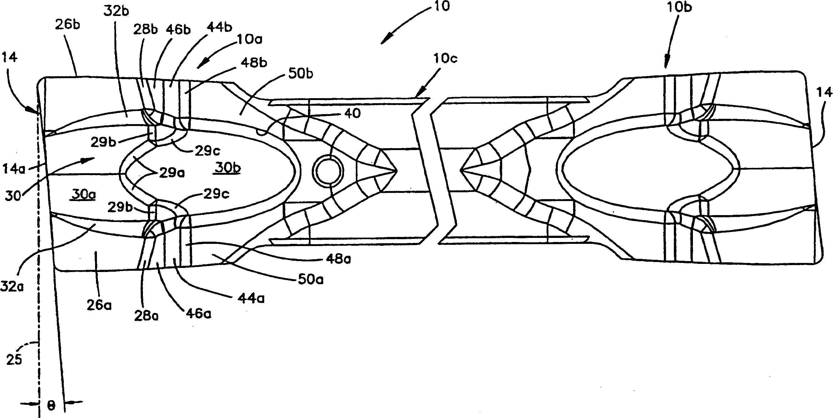
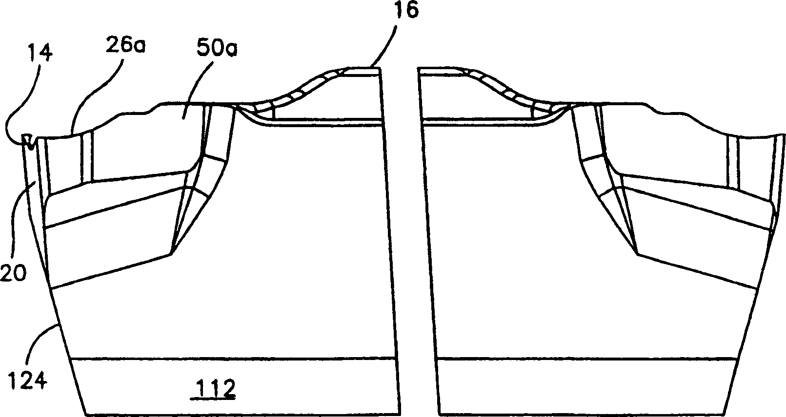
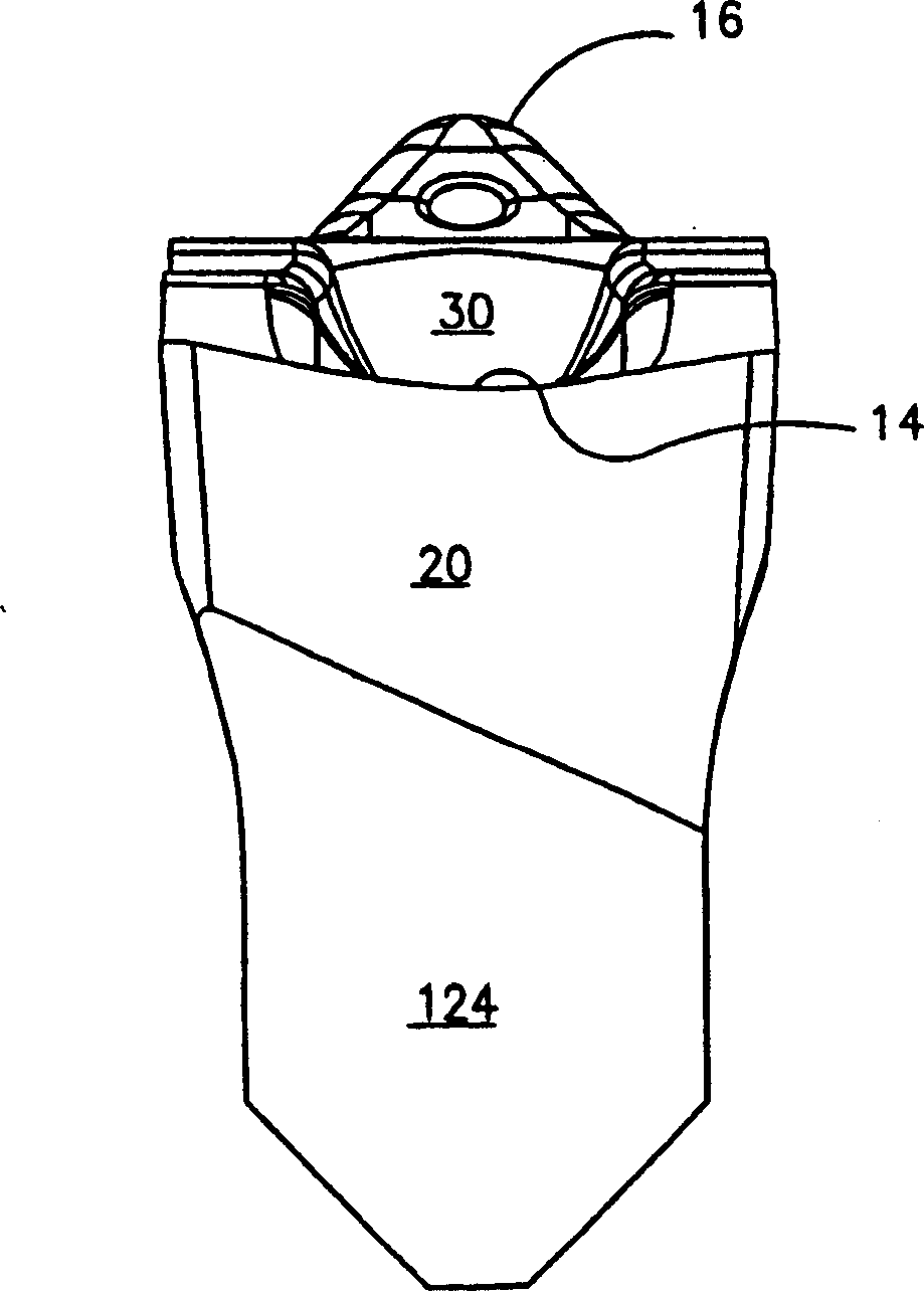
[0026] Figures 1 to 4 The general structure of a metal cutting insert 10 constructed in accordance with a preferred embodiment of the present invention is shown. In use, the blade 10 is clamped in the tool holder 100 (see Image 6 ). Generally speaking, the toolholder forms part of a sliding mechanism that positions the cutting edge 14 of the cutting insert 10 in contact with a rotating workpiece (not shown) for performing a cutting operation on the workpiece.

[0027] In the disclosed embodiment, the blade 10 includes a pair of cutting portions 10a, 10b on either side of a shank 10c. In use, the shank 10c of the blade 10 is clamped to the tool holder 100 (as Image 6 ), the toolholder 100 positions and supports one of the cutting parts, namely 10a, in a machining position. After this cutting portion 10a is worn, the insert 10 is rotated by 180° in the tool holder 100 in order to position the other cutting portion 10b in th...


PUM


Abstract

A metal cutting insert having a pair of cutting portions disposed on both sides of a shank, each cutting portion having a front clearance surface with a cutting edge formed on its upper edge. A pair of spaced apart chip breaking surfaces originate at or near the cutting edge and extend therefrom. A pair of second chip breaking surfaces are located downstream of the first chip breaking surfaces and are interconnected with the associated first chip breaking surfaces by transition surfaces. A central channel is located between the chip breaking faces and includes an entry portion beginning at or near the cutting edge. When the chip is cut from the rotating workpiece, the first chip breaking surface forms the initial curl of the chip, while the groove can promote the hardening of the middle part of the chip. The second chip breaking surface further curls the chip to reduce the curl diameter of the chip. A toolholder for securely mounting a metal cutting insert includes a base and a clamping arm forming with the base a clearance for receiving one of the cutting portions of the cutting insert. The toolholder includes first and second planar abutment surfaces. One of the abutment surfaces is for face-to-face engagement with a locating surface formed by a cutting portion of a cutting edge having a lead angle of non-zero degrees; The positioning faces are engaged face-to-face.

Description

technical field [0001] The present invention relates generally to metalworking and, in particular, to a metal cutting insert and a cartridge for holding a metal cutting insert. Background technique [0002] Metal cutting inserts having a wide variety of chip control shapes are known in the art. U.S. Patent No. 3,654,681 discloses a metal cutter characterized in that its cutting portion is provided with a chip breaking surface comprising opposing chamfers behind the cutting edge which help provide Clearance for crumb purposes. US Patent No. 3815191 describes a chip shaping insert which imparts longitudinally extending bulges to the chip to harden and change the shape of the chip. US Patent No. 3,973,308 describes a cutting tool having several recesses or recesses spaced apart from each other and inwardly of and spaced from the cutting edge. US Patent No. 4,629,372 to Huston discloses a cutting insert with a chip breaking surface that can be used as a parting or parting off...

Claims


Application Information

Patent Timeline
Patent Type & Authority Applications(China)
IPC IPC(8): B26D3/00B23B27/04B23B29/04B23P
CPCB23B27/045B23B29/043B23B2200/087B23B2200/202B23B2205/02Y10T407/235Y10T407/245Y10T407/23Y10T407/24
Inventor V·辛普森三世N·P·C·童
Owner KENNAMETAL INC
Why Eureka
Try Eureka