Method of generating ejection pattern data, and head motion pattern data; apparatus for generating ejection pattern data; apparatus for ejecting functional liquid droplet; drawing system; method of manufacturing organic el device, electron emitting device, pdp device, electrophoresis display device, color filter, and organic el; and method of forming spacer, metal wiring, lens, resist, and light diffuser

a technology of ejection pattern and data, which is applied in the field head motion pattern data, can solve the problems of practicability of generating ejection pattern data, and achieve the effect of convenient generation

Inactive Publication Date: 2005-03-08
KATEEVA
View PDF1 Cites 10 Cited by
  • Summary
  • Abstract
  • Description
  • Claims
  • Application Information

AI Technical Summary

Benefits of technology

This invention has a feature of providing: a method of generating ejection pattern data in which ejection pattern data for each nozzle can be easily generated when an image is drawn by selectively ejecting functional liquid droplets from a plurality of nozzles arranged in an array in a plurality of functional liquid droplet ejection heads; and a method of generating head motion pattern data; an apparatus for generating ejection pattern data, and an apparatus for ejecting functional liquid droplets; a drawing system; a method of manufacturing a liquid crystal display device, a method of manufacturing an organic EL device, a method of manufacturing an electron emitting device, a method of manufacturing a PDP device, a method of manufacturing an electrophoresis display device, a method of manufacturing a color filter, and a method of manufacturing an organic EL; and a method of forming a spacer, a method of forming metal wiring, a method of forming a lens, a method of forming a resist, and a method of forming a light diffuser.
According to this arrangement, it is possible to draw chip-forming areas based on ejection pattern data generated based on a color-by-color basis by the plurality of functional liquid droplet ejection devices. That is, even when drawing in one color is carried out by a single functional liquid droplet ejection device (functional liquid droplet ejection head), it is possible to collectively generate ejection pattern data for a plurality of colors easily and quickly.

Problems solved by technology

However, the amount of ejection pattern data for the twelve arrays of nozzles is enormous so that it is practically impossible to generate ejection pattern data by the conventional method of generating ejection pattern data for each of the nozzle arrays.

Method used


Image

  • Method of generating ejection pattern data, and head motion pattern data; apparatus for generating ejection pattern data; apparatus for ejecting functional liquid droplet; drawing system; method of manufacturing organic el device, electron emitting device, pdp device, electrophoresis display device, color filter, and organic el; and method of forming spacer, metal wiring, lens, resist, and light diffuser
  • Method of generating ejection pattern data, and head motion pattern data; apparatus for generating ejection pattern data; apparatus for ejecting functional liquid droplet; drawing system; method of manufacturing organic el device, electron emitting device, pdp device, electrophoresis display device, color filter, and organic el; and method of forming spacer, metal wiring, lens, resist, and light diffuser
  • Method of generating ejection pattern data, and head motion pattern data; apparatus for generating ejection pattern data; apparatus for ejecting functional liquid droplet; drawing system; method of manufacturing organic el device, electron emitting device, pdp device, electrophoresis display device, color filter, and organic el; and method of forming spacer, metal wiring, lens, resist, and light diffuser

Examples


Embodiment Construction

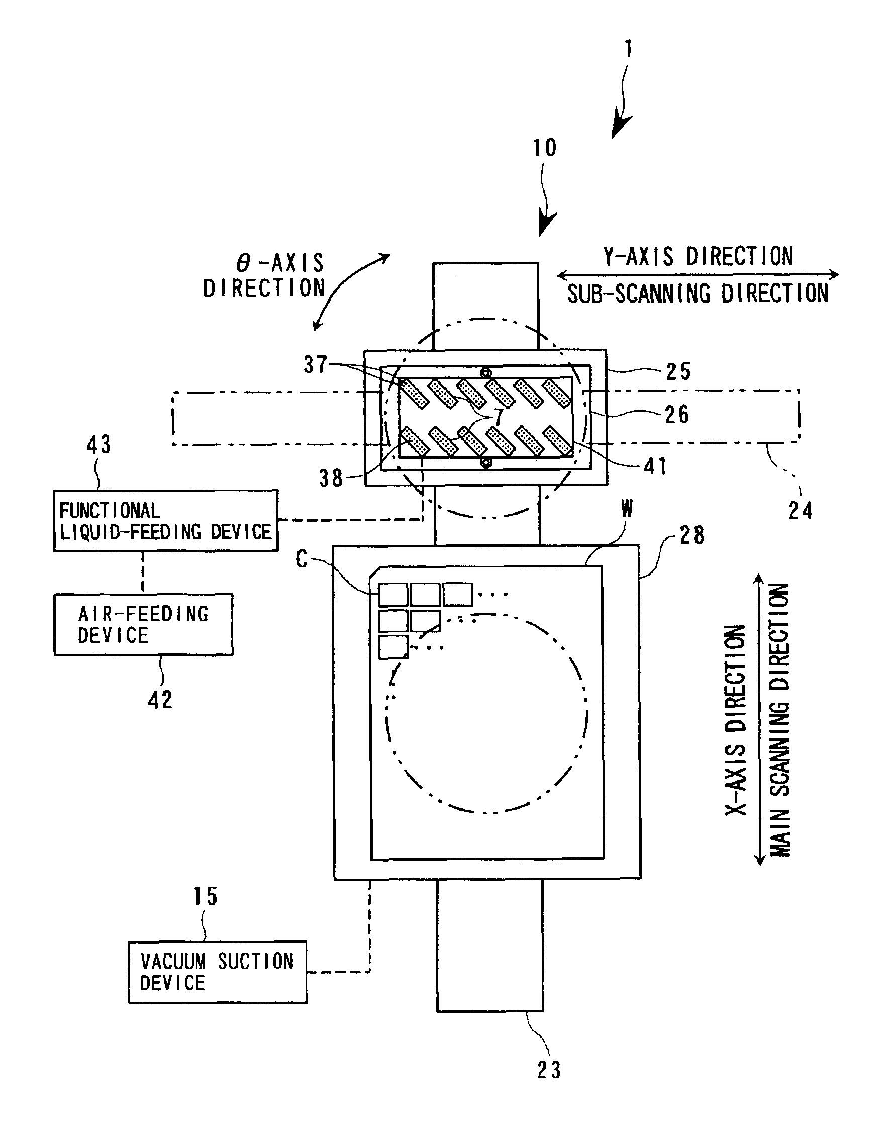
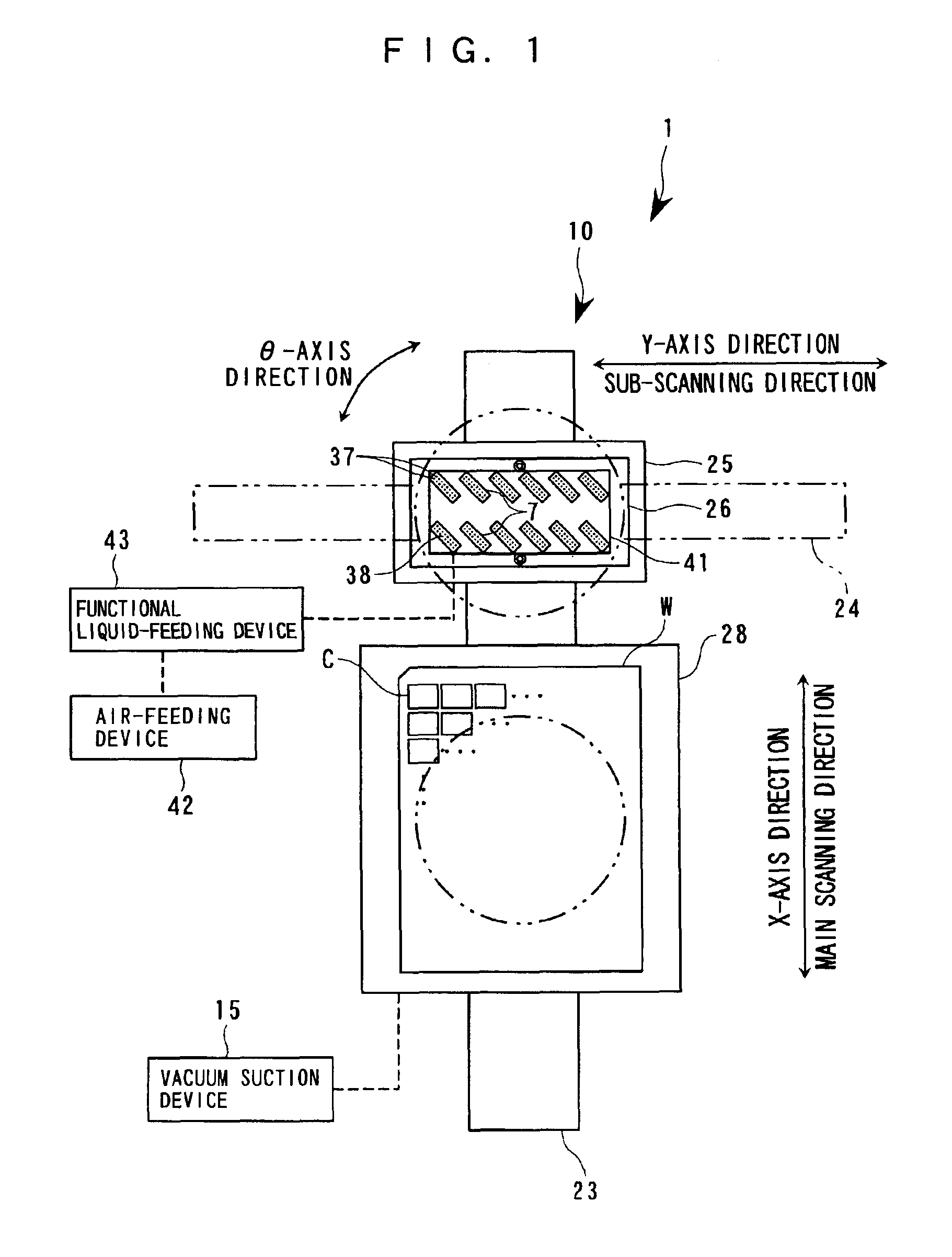
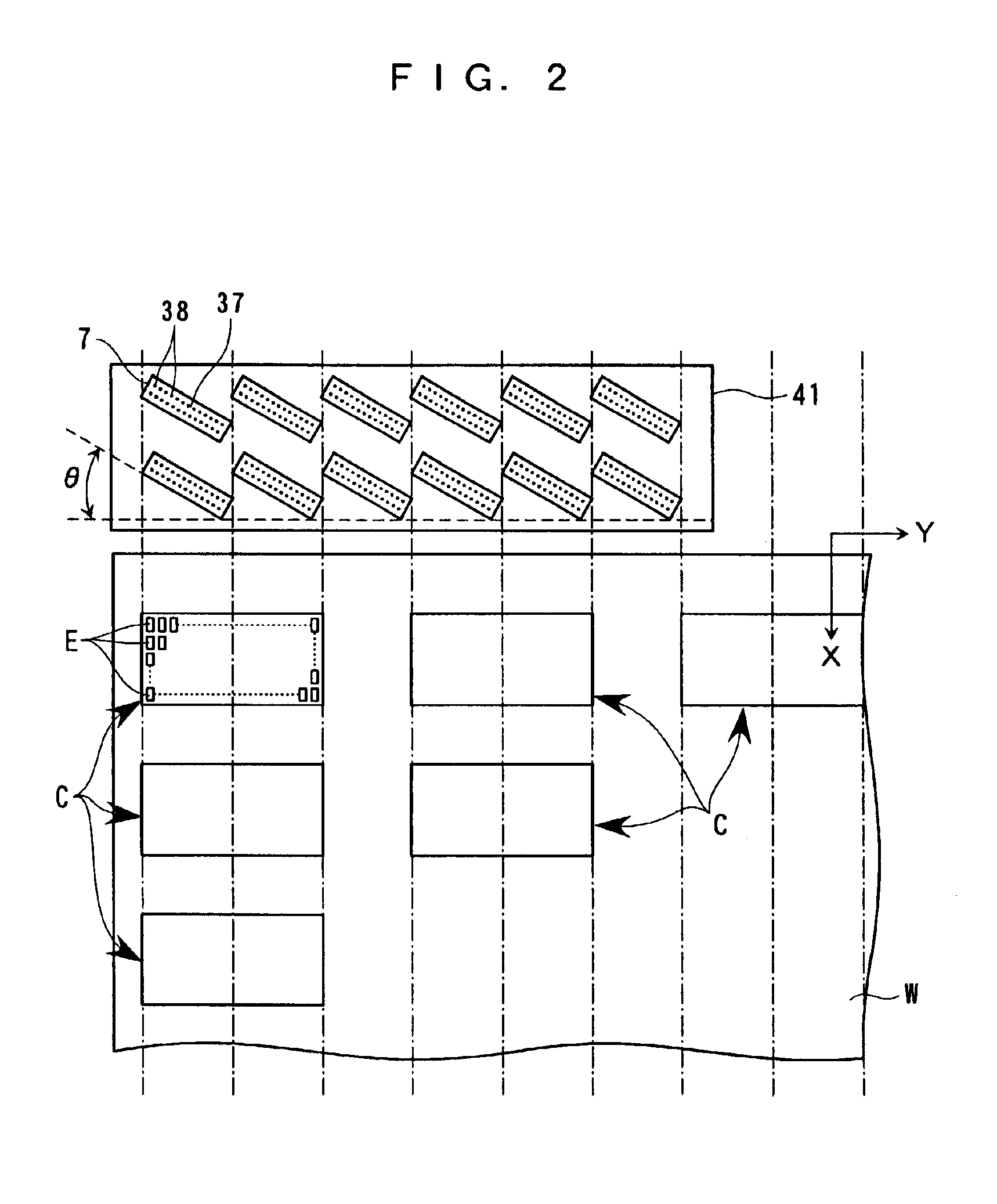
The invention will now be described in detail with reference to the drawings showing a preferred embodiment thereof. A functional liquid droplet ejection device as a component of a drawing system is capable of accurately ejecting very small ink droplets such that the droplets are formed into dots, from a plurality of nozzles arranged on a functional liquid droplet ejection head of the device. Hence, it is expected that the functional liquid droplet ejection device can be applied to various fields of manufacturing component parts by using special inks, photosensitive or light-emitting resins, etc. as functional liquids.

An ejection pattern data-generating device, a head motion pattern data-generating device, the functional liquid droplet ejection device, and the drawing system according to the present embodiment are applied, for instance, to a manufacturing system for manufacturing so-called flat displays, such as a liquid crystal display device and an organic EL device. The manufactu...


PUM

PropertyMeasurementUnit
widthaaaaaaaaaa
lengthaaaaaaaaaa
thicknessaaaaaaaaaa

Abstract

A method of generating ejection pattern data for a plurality of nozzles for use in selectively ejecting functional liquid droplets from the nozzles is to draw on ore more one chip-forming area on a workpiece. The method includes a pixel-setting step of setting pixel information concerning an array of pixels in the chip-forming areas, a chip-setting step of setting chip information concerning an array of the chip-forming areas on the workpiece, a nozzle-setting step of setting nozzle information concerning an array of the nozzles, and a data-generating step of generating the ejection pattern data for the nozzles from the pixel information, the chip information, and the nozzle information, based on a positional relationship between the workpiece and the functional liquid droplet ejection head. The ejection pattern data are easily and quickly generated for the nozzles arranged in an array in the plurality of functional liquid droplet ejection heads.

Description

BACKGROUND OF THE INVENTION1. Field of the InventionThis invention relates to: a method of generating ejection pattern data for selectively ejecting a functional liquid droplet from a functional liquid ejection head to a work or workpiece, and a method of generating head motion pattern data; an apparatus for generating ejection pattern data, and an apparatus for ejecting functional liquid droplets; a drawing system; a method of manufacturing a liquid crystal display device, a method of manufacturing an organic electroluminescence (EL) device, a method of manufacturing an electron emitting device, a method of manufacturing a plasma display panel (PDP) device, a method of manufacturing an electrophoresis display device, a method of manufacturing a color filter, and a method of manufacturing an organic EL; a method of forming a spacer, a method of forming metal wiring, a method of forming a lens, a method of forming a resist, and a method of forming a light diffuser.2. Description of t...

Claims


Application Information

Patent Timeline
Patent Type & Authority Patents(United States)
IPC IPC(8): H01L51/40H01L51/05H05K3/12B41J2/01B05C5/00B05C11/10B05D1/26B05D3/00B05D7/00B41J2/145G02F1/13G02F1/1335G05B19/4099G09F9/00H01J9/227H01J11/22H01J11/34H01J11/42H01L51/50H05B33/10
CPCG05B19/4099H05K3/1241H01L51/0004G05B2219/49015H10K71/13B41J2/01
Inventor OGAWA, MASAHIKOKATO, TSUYOSHI
Owner KATEEVA
Why Eureka
Try Eureka