

Adhesive chuck device
A technology for chucks and components, which is applied in the directions of optical/shielding devices, transportation and packaging, tube structure parts, etc., can solve the problems of high manufacturing cost and difficulty in manufacturing large-sized electrostatic chucks, and achieve simple peeling mechanism and reduce The incidence of failure and the effect of reducing manufacturing costs
- Summary
- Abstract
- Description
- Claims
- Application Information
AI Technical Summary
Problems solved by technology
Method used
Image

Examples
Embodiment approach 1
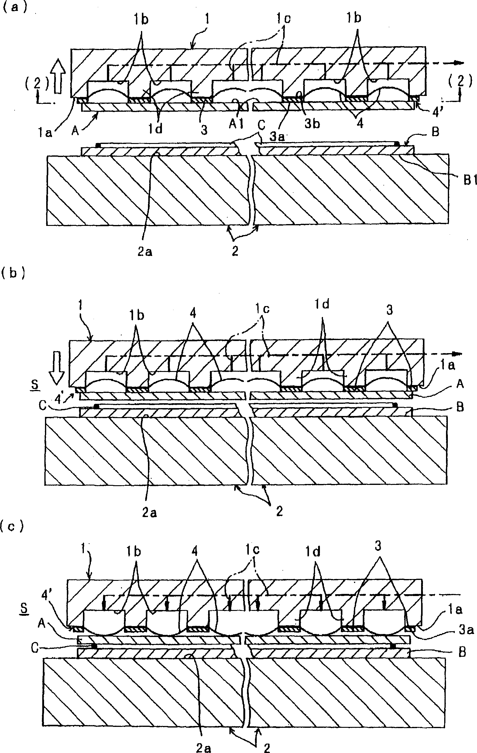
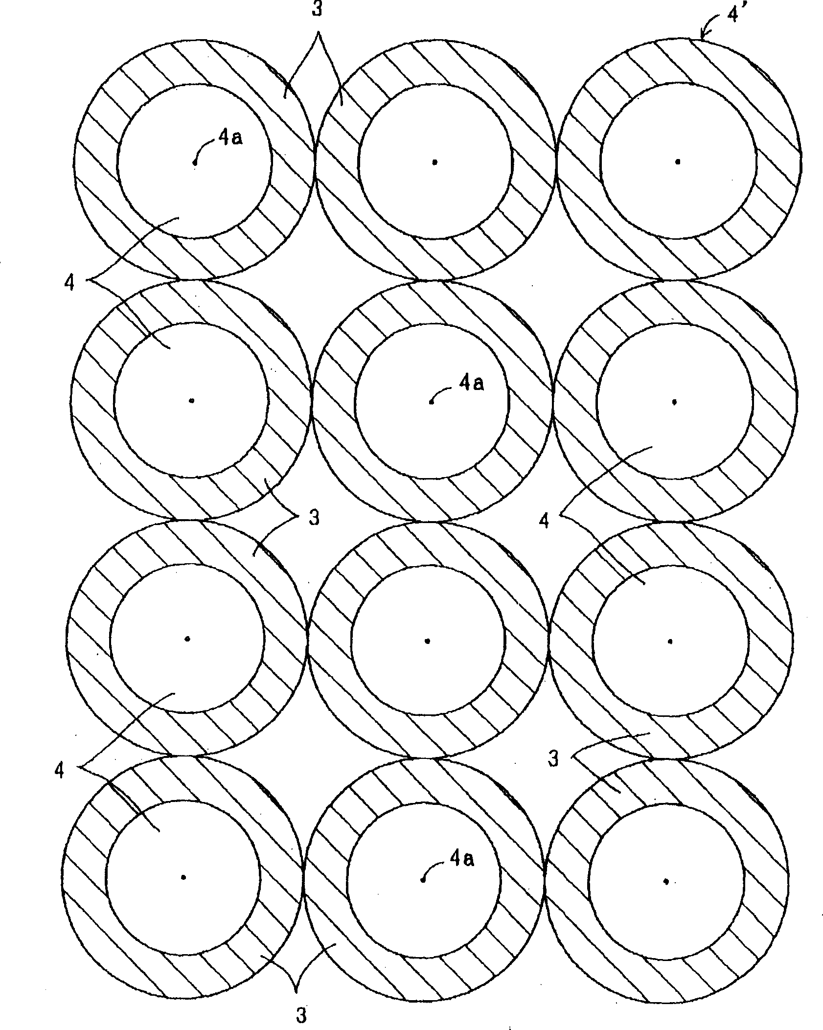
[0050] The Example 1, as Figure 1 ~ Figure 2 As shown, the following situation is shown, that is, the upper and lower holding plates 1, 2 are flat plate platforms formed by rigid bodies such as metals, ceramics, etc., so that there is no bending (bending) deformation, and only the upper holding plate 1 of these The substrate side is covered by a plate-shaped body 4' composed of a plurality of bonding members 3 and a plurality of deformable films (pressurized films) 4, which hold the plate 1 from the substrate side by utilizing pressurization. The protrusion (convex shape) is deformed, whereby the upper substrate A is forcibly pulled away from the bonding surface 3 a of the bonding member 3 to perform peeling.
[0051] On the holding surface 1a of the upper holding plate 1, a plurality of or single recesses 1b are recessed, and these recesses 1b are connected with suction sources (not shown) such as vacuum pumps, compressors, etc. The operation of the gas source discharges th...
Embodiment approach 2
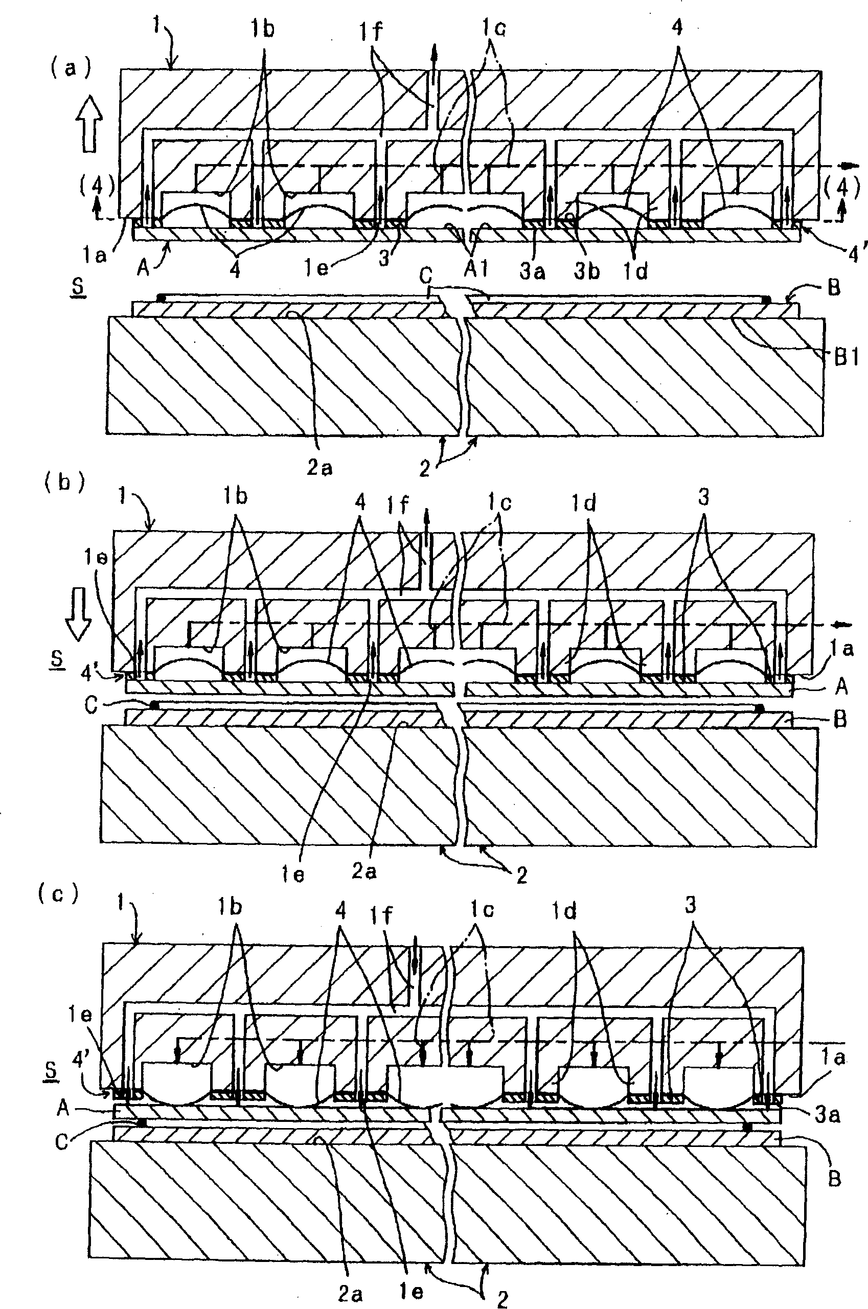
[0071] The embodiment 2 as Figure 3 ~ Figure 4 As shown, from the partition wall 1d formed on the holding surface 1a of the aforementioned holding plate 1 throughout the bonding member 3 and the deformable film 4, a plurality of air holes 1e are opened in a penetrating shape, and these air holes 1e are communicated with, for example, a vacuum pump, a compressor, etc. The ventilation passage 1f of the suction source (not shown in the figure) of the machine etc. is formed in a different system from the ventilation passage 1c of the aforementioned recessed portion 1b. This structure is different from the aforementioned Figure 1 ~ Figure 2 The shown embodiment 1 is different, other structures are with Figure 1 ~ Figure 2 Example 1 shown is the same.
[0072] According to the above composition, if image 3 As shown in (a), when the upper substrate A is placed on the holding surface 1a of the upper holding plate 1, the upper substrate A can be sucked and held with a stronger fo...
Embodiment approach 3
[0075] The Example 3, as Figure 5 ~ Figure 6 As shown, the following structure is the same as the aforementioned Figure 1 ~ Figure 2 Shown in Example 1 and Figure 3 ~ Figure 4 The shown embodiment 2 is different, in addition to other structures and Figure 1 ~ Figure 2 Shown in Example 1 and Figure 3 ~ Figure 4 The shown embodiment 2 is the same, and the different structure is: instead of the above-mentioned ring-shaped bonding member 3, a bonding member 3' is set on a part of the aforementioned deformable membrane 4, so as to constitute a plurality of deformable membranes 4 The plate-like body 4 " that constitutes with the bonding member 3 ' covers the substrate side of the upper holding plate 1 by the plate-shaped body 4 ", and at the same time, in the state where the deformable film 4 is made flat, the bonding member 3 ' The adhesive surface 3a' is brought into contact with the upper substrate A to be bonded and held, and on the other hand, the deformable film 4 is d...
PUM
 Abstract
Description
Claims
Application Information