Intelligent electric stop valve for three-way flow proportional distribution

A proportional distribution, intelligent electric technology, applied in the direction of multi-way valves, valve details, valve devices, etc., can solve the problems of inability to apply management network systems, remote monitoring and adjustment, etc., to achieve small size, simple structure, and large flow capacity Effect

Inactive Publication Date: 2006-05-31
甘肃德邦智能机电科技有限公司
View PDF2 Cites 9 Cited by
  • Summary
  • Abstract
  • Description
  • Claims
  • Application Information

AI Technical Summary

Problems solved by technology

The flow setting or flow adjustment of the above two patents can only be adjusted manually, and cannot be remotely monitored and adjusted through control equipment such as computers. Therefore, it cannot be applied to the management network system of central heating automatic control.

Method used


Image

  • Intelligent electric stop valve for three-way flow proportional distribution
  • Intelligent electric stop valve for three-way flow proportional distribution
  • Intelligent electric stop valve for three-way flow proportional distribution

Examples


Embodiment Construction

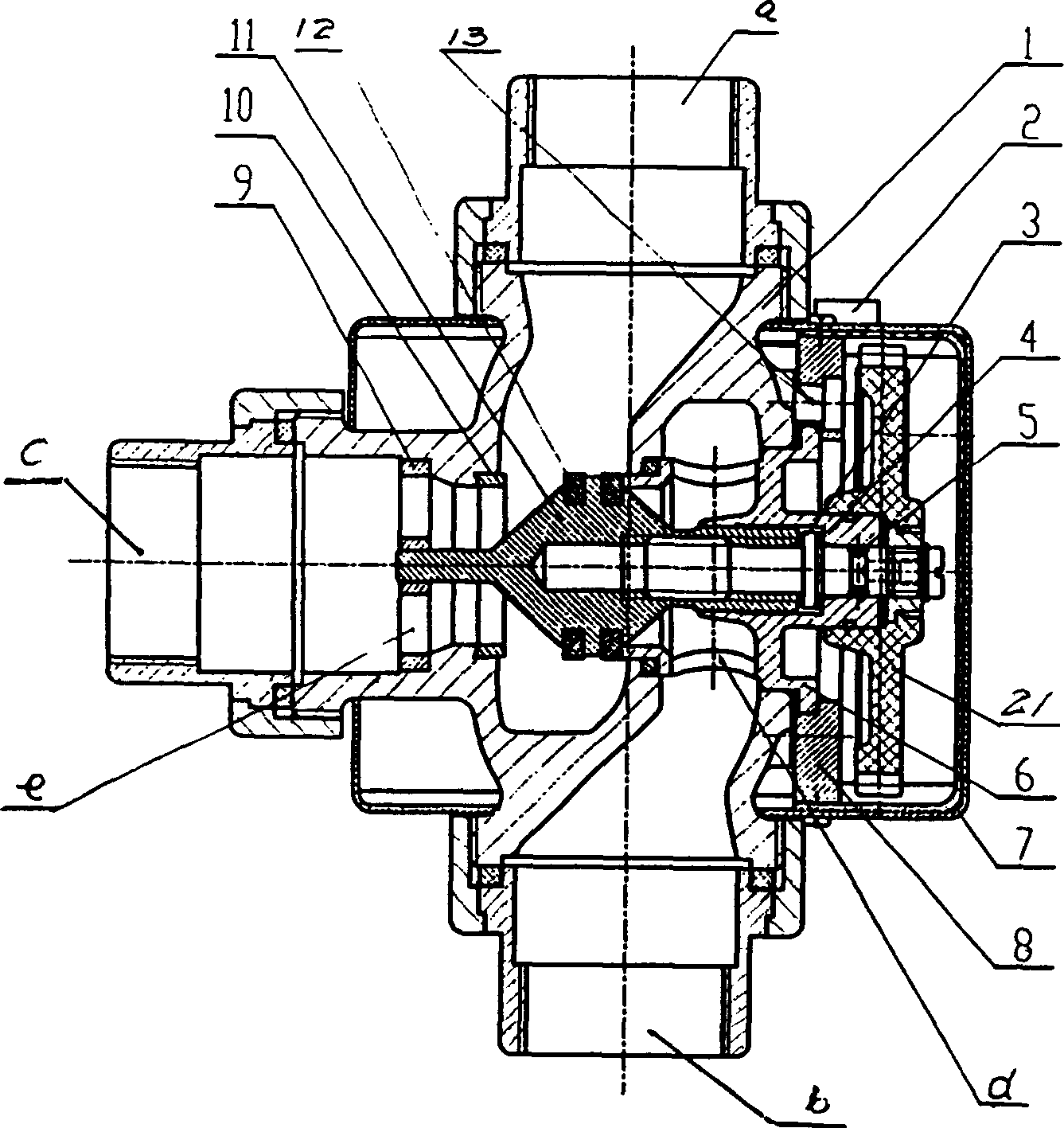
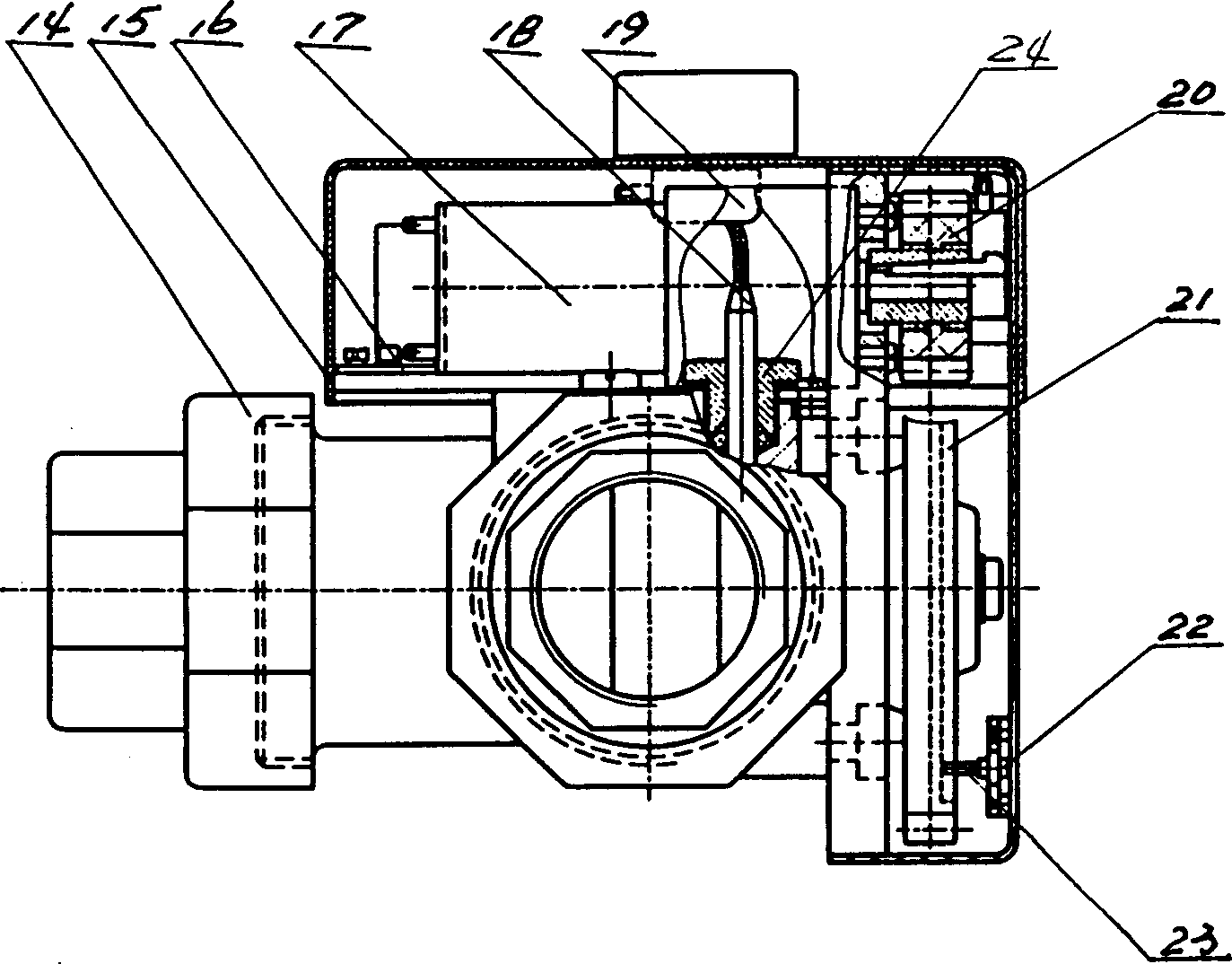
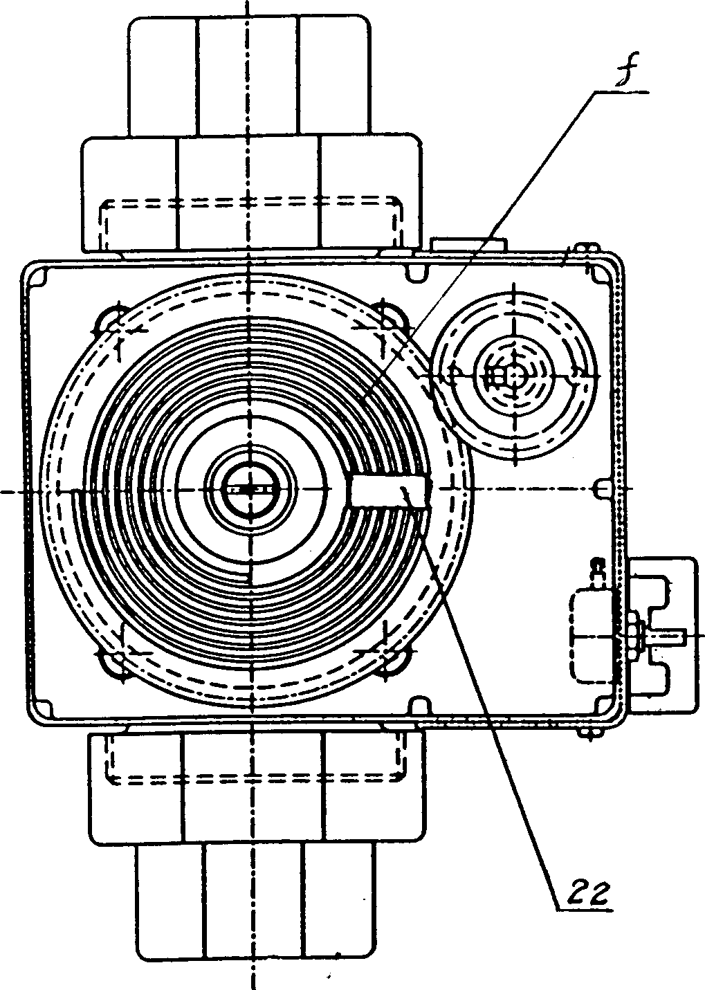
[0018] See figure 1 , figure 2 , image 3 ,, the intelligent electric three-way flow proportional distribution cut-off valve has a valve body 1 fixedly connected to the liquid inlet a, liquid outlet b and bypass liquid outlet c, the motor 17 is fixedly connected to the connecting plate 8, and its shaft and gear 20 is fixedly connected, the gear 20 meshes with the gear 21, and the gear 21 is fixedly connected with the valve stem 3; 1 connection, the connection between the valve core 11 and the upper cover 6 is a hexagonal prism connection. The valve stem 3 is provided with a valve core 11; the inner hole of the valve core 11 is provided with an internal thread, which is threadedly connected with the valve stem 3; the guide seat 9 with a through hole e is arranged under the valve core 11, and a guide Hole, in which the lower end of the valve core 11 is inserted; the through hole e of the guide seat 9 is a fan-shaped hole. The valve body sealing seat ring 10 is set at the in...


PUM


Abstract

The invention relates to a flow control valve for use in the heating plant, which consists of a valve body connected with an liquid inlet, an outlet and a bypass liquid outlet. The generator is firm-jointed on the connection board and its shaft is firm-jointed with the gear. The gear is connected with the valve stem. The top cover interlinked on the valve stem and the spool is firm-jointed on the valve body via the connection board. The spool is disposed on the valve stem. The internal thread disposed in the inner hole of the spool is connected with the thread of the valve stem. A guide seat with the through-hole is disposed under the spool and in its centre is set the guide hole, into which is inserted the bottom end of the spool. The sealing seat ring of the valve body disposed in the inner cavity of the bypass liquid outlet is closed with the sealing washer on the spool.

Description

Technical field: [0001] The invention mainly relates to heating and flow control valves in heating equipment. Background technique: [0002] In the user heating pipelines connected in series at present, it is impossible or difficult to realize automatic adjustment and control of heat energy. Utility model patents ZL00231495.9 titled "Flow Control Valve" and ZL00264596.3 titled "Mechatronic Three-way Flow Proportional Distribution Stop Valve" respectively disclose a flow control valve. The flow setting or flow adjustment of the above two patents can only be adjusted manually, and cannot be remotely monitored and adjusted through control equipment such as a computer. Therefore, it cannot be applied to the management network system of central heating automatic control. Invention content: [0003] The purpose of the present invention is to avoid the disadvantages of the prior art and provide an intelligent electric three-way flow proportional distribution cut-off valve. The ...

Claims


Application Information

Patent Timeline
Patent Type & Authority Applications(China)
IPC IPC(8): F16K11/044F16K31/05
Inventor 鲍侃田亚菲俞光
Owner 甘肃德邦智能机电科技有限公司
Why Eureka
Try Eureka