Check patentability & draft patents in minutes with Patsnap Eureka AI!

Coating device of demoulding agent of mould

A coating device and release agent technology, applied in the direction of spraying device, electrostatic spraying device, etc., can solve the problems of large spray volume, stickiness around moisture, and high cost of water-based release agent

Inactive Publication Date: 2006-06-07
LUI
View PDF1 Cites 12 Cited by
  • Summary
  • Abstract
  • Description
  • Claims
  • Application Information

AI Technical Summary

Problems solved by technology

[0007] However, in the conventional mold release agent coating device, when switching from the generally used water-based release agent to the oil-based release agent, if the oil-based release agent is sprayed in a mist form only by hydraulic pressure or air pressure , it will generate a lot of moisture and cause the surroundings to become sticky
Therefore, the operator must wear, for example, rubber work clothes and hats for work, and there is a problem of poor work environment and work efficiency.
In addition, in conventional mold release agent coating devices, oil-based mold release agents have the same problem of low coating efficiency as water-based mold release agents.
[0008] In addition, when using an oil-based release agent, the cost of the oil-based release agent is about 100 times that of a water-based release agent. In the existing mold release agent coating device, the injection amount of the release agent is about 180cc / min. The injection volume is large, so there is a problem that the cost is greatly increased compared to water-based release agents
In addition, if a large amount of mold release agent is sprayed, the result may cause damage to the environment

Method used


Image

  • Coating device of demoulding agent of mould
  • Coating device of demoulding agent of mould
  • Coating device of demoulding agent of mould

Examples


no. 1 Embodiment approach

[0028] A mold release agent coating device 1 according to a first embodiment of the present invention will be described with reference to FIGS. 1 and 2 . A description will be given using, for example, the mold 3 for injection molding as the object to be coated. This injection mold 3 is configured by vertically arranging a pair of first mold 3A and second mold 3B, and a cavity is formed on each molding surface 5 of the first and second molds 3A, 3B. As shown in FIG. 1 , a pair of first and second dies 3A and 3B are arranged at a predetermined interval so that the molding surfaces 5 of the first and second dies 3A and 3B face each other.

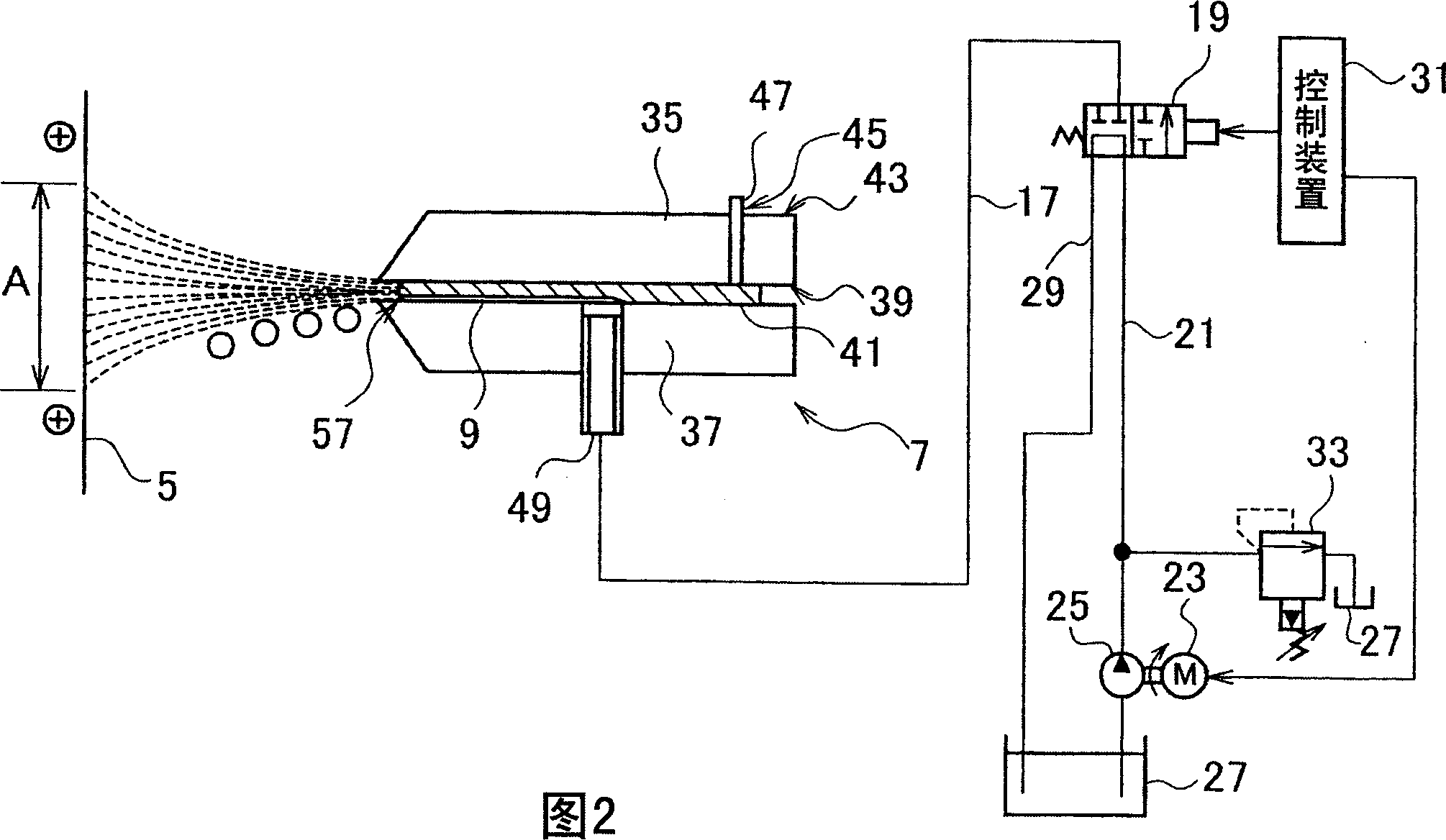
[0029] In addition, the mold release agent coating device 1 according to the first embodiment of the present invention is an electrostatic type. Equipped with the ejection channel group 9 for ejecting the oil-based release agent to the molding surfaces 5 of the first and second molds 3A, 3B, and the nozzle 7 for applying high voltage to char...

no. 2 Embodiment approach

[0057] In the above-mentioned first embodiment, an example in which an oil-based mold release agent is applied to the molding surfaces 5 of the pair of first and second molds 3A, 3B constituting the mold 3 for injection molding on both sides of the nozzle 7 is described. It is applicable to multiple pairs of molds 3 with the nozzle 7 sandwiched in the middle and arranged oppositely on both sides of the nozzle 7 .

[0058] Figure 4 It is a plan view of the mold release agent coating device 1 according to the second embodiment of the present invention. For example, two pairs of molds 3 are arranged facing each other at a predetermined interval with the nozzles 7 interposed therebetween. At this time, the molding surfaces 5 sides of the molds 3 of the two pairs are arranged to face each other.

[0059] In addition, the inversion (turning) angle of the nozzle 7 is not limited to 180° as in the above-mentioned embodiment, and can be inverted at any angle. In addition, since the n...


PUM

PropertyMeasurementUnit
Thicknessaaaaaaaaaa

Abstract

The invention relates to a mold release agent coating device. The mold release agent coating device (1) is arranged so that the molding surface (5) side of at least one pair of molds (3) faces each other with a predetermined interval therebetween. Support members (11, 13) supporting nozzles (7) that apply a high voltage to charge the oil-based mold release agent and spray it onto the molding surface (5) of each mold (3) are arranged in the space. While the supporting members (11, 13) move back and forth freely along the length direction of the mold (3), in order to make the nozzle (7) face the molding surface (5) of each mold (3), the length direction of the relative mold (3) is along the The supporting members (11, 13) are rotatably arranged in an almost vertical direction.

Description

technical field [0001] The present invention relates to a mold release agent coating device, in particular to a mold release agent coating device for uniformly coating an oily release agent on a molding surface of a mold with an appropriate amount. Background technique [0002] Conventionally, molds for injection molding, for example, molds for injection molding or die casting are composed of a pair of first mold and second mold, and the cavity molded part is formed by the molding surfaces of the first mold and the second mold. For example, molten resin is injected into the cavity forming part to form a resin product. At this time, in order to improve the releasability of the molded product molded in the cavity molding part and to prevent sand sticking to the mold, a mold release agent is applied to the molding surface of the mold before injection molding. [0003] As a conventional mold release agent coating device, for example, the mold release agent is sprayed onto the m...

Claims


Application Information

Patent Timeline
IPC IPC(8): B05B13/04B05B5/00B05B15/06B29C33/58
Inventor 大和田弘
Owner LUI
Features
  • R&D
  • Intellectual Property
  • Life Sciences
  • Materials
  • Tech Scout
  • Unparalleled Data Quality
  • Higher Quality Content
  • 60% Fewer Hallucinations
Learn More