Liquid crystal display

A technology of liquid crystal display and thin film transistor, which is applied in the direction of static indicators, instruments, transistors, etc., and can solve the problem of increasing the load of gate lines 11, and achieve the effect of increasing load and power consumption, and improving display quality

Inactive Publication Date: 2006-06-07
HONG FU JIN PRECISION IND (SHENZHEN) CO LTD +1
View PDF1 Cites 2 Cited by
  • Summary
  • Abstract
  • Description
  • Claims
  • Application Information

AI Technical Summary

Problems solved by technology

However, arranging a plurality of elongated storage electrodes 14 on the gate line 11 will increase the load on the gate line 11 at the same time.

Method used


Image

  • Liquid crystal display
  • Liquid crystal display
  • Liquid crystal display

Examples


Embodiment Construction

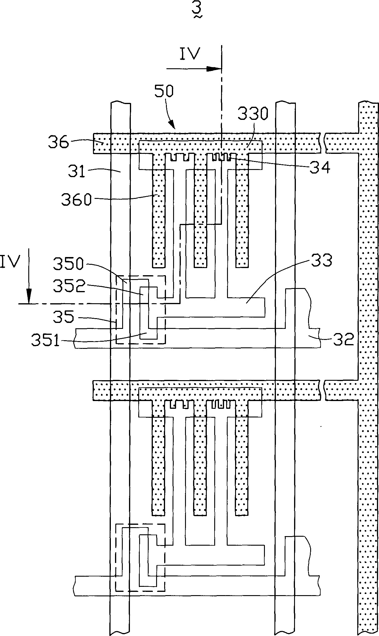
[0014] A pixel region of the liquid crystal display of the present invention such as image 3 with Figure 4 as shown, image 3 It is a plan view of a pixel area of ​​the liquid crystal display of the present invention, Figure 4 yes image 3 Sectional view along line IV-IV.

[0015] see image 3 , the pixel area 3 includes a gate line 32 extending laterally, a data line 31 extending vertically, a thin film transistor 35 located at the intersection of the gate line 32 and the data line 31, a thin film transistor 35 substantially parallel to the gate line The common line (CommonLine) 36 of the electrode line 32 and the pixel electrode 33 , two adjacent data lines 31 and two gate lines 32 cross each other to form the pixel region 3 .

[0016] Wherein, the thin film transistor 35 includes a gate 350 , a drain 351 and a source 352 . The gate line 32 is electrically connected to the gate 350 and provides a control signal thereto, while the data line 31 is electrically connect...


PUM


Abstract

The present invention discloses a kind liquid crystal display, which has one base plate including one insulating substrate, one common line on the insulating substrate, one common electrode connected to the common line, one pixel electrode and one dielectric layer between the common line and the pixel electrode. The common line has several lugs to form one storage capacitor together with the upside pixel electrode and the dielectric layer. In the liquid crystal display, the storage capacitor does not result in load and power consumption of the driving circuit.

Description

【Technical field】 [0001] The invention relates to a liquid crystal display. 【Background technique】 [0002] A liquid crystal display adopting an active matrix array generally includes a plurality of pixel regions formed by intersecting gate lines and source lines and a plurality of thin film transistors (Thin Film Transistor, TFT) arranged at the intersections of gate lines and source lines, Wherein, each pixel has a pixel electrode, and the thin film transistor is used to control the switching of the pixel electrode. [0003] When a signal is applied to the thin film transistor, the pixel area is activated, and an image signal is applied to the pixel electrode. In order to achieve a high-quality display effect, the voltage applied to the pixel electrode must maintain a constant value until the next signal is received. However, the charge used to maintain the voltage on the pixel electrode usually leaks quickly, causing the voltage on the pixel electrode to drop prematurel...

Claims


Application Information

Patent Timeline
Patent Type & Authority Applications(China)
IPC IPC(8): G02F1/136G02F1/133H01L29/786
Inventor 洪肇逸陈弘育
Owner HONG FU JIN PRECISION IND (SHENZHEN) CO LTD
Why Eureka
Try Eureka