Counter device and counting method

A counting method and counter technology, which can be applied in the fields of instruments, electrography, optics, etc., can solve problems such as difficult to carry, and achieve the effects of increasing costs, increasing costs, and reducing the burden on devices

Inactive Publication Date: 2006-06-07
KYOCERA DOCUMENT SOLUTIONS INC
View PDF2 Cites 11 Cited by
  • Summary
  • Abstract
  • Description
  • Claims
  • Application Information

AI Technical Summary

Problems solved by technology

[0007] However, in the aforementioned prior art, since the number of bits = the maximum counter value, the number of bits corresponding to the maximum count value is required
For example, in the

Method used


Image

  • Counter device and counting method
  • Counter device and counting method
  • Counter device and counting method

Examples


Example Embodiment

[0027] An embodiment of the present invention will be described below with reference to the drawings.

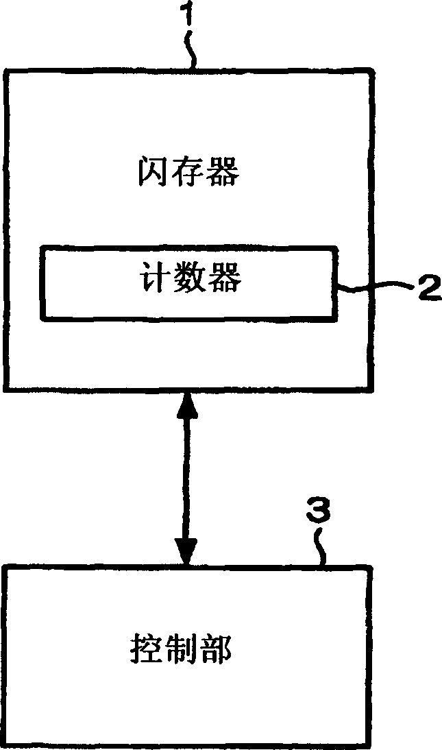
[0028] FIG. 1 is a block diagram showing a counter device according to a first embodiment of the present invention. The flash memory 1 is a nonvolatile memory, and has a counter 2 . The counter 2 is constituted by a predetermined number of bits, and counts the accumulated number of times of rewriting. The control unit 3 controls data writing and data reading of the counter 2 . In the following, for simplification of description, the number of bits of the counter 2 is set to 8 bits (1 byte), but the present invention is not limited thereto, as long as the required number of bits can be appropriately ensured according to the maximum count value.

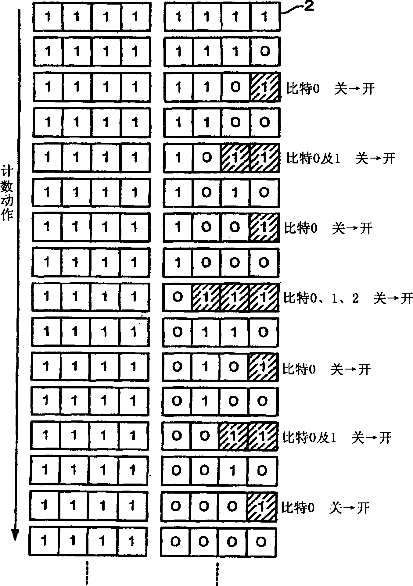
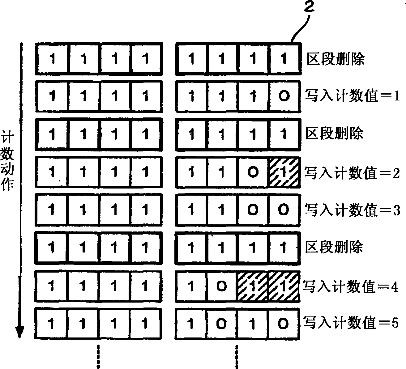
[0029] Next, FIG. 2 is a conceptual diagram for explaining the operation of the aforementioned counter device. In this embodiment, the counter value is managed as a 1's complement. First, as an initial setting, all the bits of th...


PUM


Abstract

A counter device having: a rewritable counter constituted by a nonvolatile memory that needs to completely convert data in a segment to high-order data before changing low-order data to high-order data in each bit The section deletion; the control unit, which controls the data writing and data reading of the aforementioned counter, wherein the aforementioned control unit performs data writing and data reading for the aforementioned counter with 1’s complement as the source number, and updates the count value.

Description

technical field [0001] The present invention relates to a counter device and a counting method using a nonvolatile memory. Background technique [0002] Printers and copiers manage a plurality of counters with a nonvolatile memory (flash memory: registered trademark). The counter is used for counting the number of printed sheets, and is also used for billing purposes, etc., so high reliability is required. However, for non-volatile memory, the more frequently used bits are, the less reliable they are. Therefore, the manufacturer generally sets the guarantee number of writes, and if the number exceeds the number, the reliability of the non-volatile memory will be significantly reduced (the manufacturer does not guarantee it). [0003] According to the device characteristics of the non-volatile memory, whenever the counter is updated, the counter value cannot be rewritten at the same location on the non-volatile memory. That is, in the non-volatile memory, the storage area ...

Claims


Application Information

Patent Timeline
IPC IPC(8): G03G21/02
Inventor 高木正刚
Owner KYOCERA DOCUMENT SOLUTIONS INC
Why Eureka
Try Eureka