
Machine oil collector-insulating board assembly for engine of vehicle

A technology of oil collector and vehicle engine, which is applied in the direction of engine lubrication, engine components, machine/engine, etc. It can solve problems such as easy loosening, affecting sealing effect, oil leakage, etc., and achieves simplified installation procedures and simplified overall Machine assembly, reducing the effect of stabilizing oil pressure

Inactive Publication Date: 2006-06-14
CHERY AUTOMOBILE CO LTD
View PDF0 Cites 3 Cited by
  • Summary
  • Abstract
  • Description
  • Claims
  • Application Information

AI Technical Summary

Problems solved by technology

Using this method to locate and install the process is more complicated
2. For the oil collector with double brackets, install the two brackets on the cylinder frame with bolts respectively. The positioning of the brackets is difficult. If the positioning of the two brackets is not accurate, the combination of the oil suction pipe of the oil collector and the frame will be affected.
The oil suction pipe of the oil collector is directly inserted into the installation hole of the oil collector on the frame, and sealed with an O-ring. When the two brackets of the oil collector are not positioned accurately, because there is a gap between the oil suction pipe and the installation hole of the oil collector on the frame. It is easy to loosen due to cooperation, which will affect the sealing effect
Therefore the oil collector-baffle plate assembly of existing vehicle engine has the following deficiencies, 1, reserve the space on the oil baffle plate to avoid the oil suction plate, reduce the oil baffle area of ​​the oil baffle plate, and affect the oil baffle plate. The oil blocking effect of the oil plate
2. When used in an oil pan with a relatively shallow oil pool, the above scheme places the oil baffle in the oil pan, and when the oil pool in the oil pan is relatively shallow, the position of the oil baffle is also placed in the oil pan At this time, because the oil baffle occupies the space of the oil sump of the oil pan, the normal oil filling quantity cannot be guaranteed
3. The installation process of the oil collector with flange surface is relatively complicated
4. If the positioning of the oil collector with double brackets is inaccurate, it will affect the sealing effect of the oil suction pipe and the oil collector installation hole on the frame, and oil leakage will easily occur

Method used


Image

  • Machine oil collector-insulating board assembly for engine of vehicle
  • Machine oil collector-insulating board assembly for engine of vehicle
  • Machine oil collector-insulating board assembly for engine of vehicle

Examples


Embodiment Construction

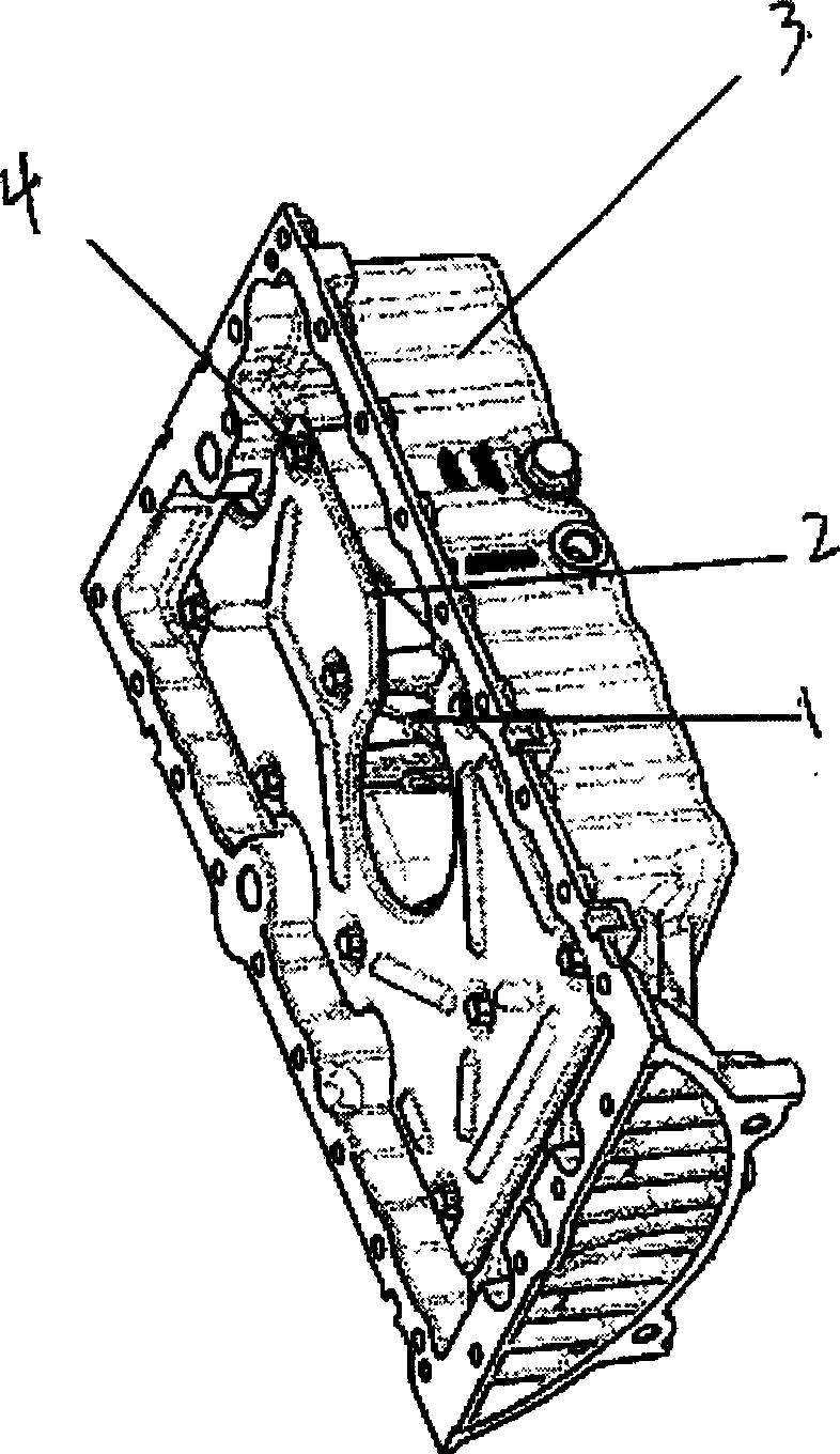
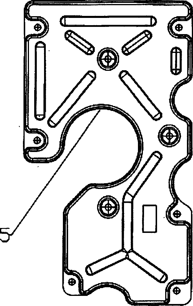
[0018] attached figure 1 It is a structural schematic diagram of the existing oil baffle plate 2 and the oil sump 1 of the oil pan, figure 2 It is a schematic diagram of the existing oil baffle structure. The oil baffle plate 2 is fixed in the oil pan and supported by the ribs 3 in the oil pan. There are bolt holes on the ribs 3 in the oil pan, and the bolts 4 can be inserted into the bolt holes 13 of the oil baffle to fix the oil baffle 2 .

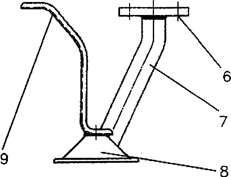
[0019] attached image 3 It is an assembly diagram of an existing oil collector with a flange face. During assembly, the flange surface 6 and the oil pump need to be fixed by two bolts, and the bracket 9 is connected to the frame with bolts.

[0020] attached Figure four It is a structural schematic diagram of an existing double-bracket oil collector. When assembling the oil collector of the double bracket, the oil suction pipe 7 is inserted into the frame, the installation hole of the oil collector adopts a clearance fit, and th...


PUM


Abstract

An engine oil collector-bulkhead assembly for the vehicle engine includes an oil sump, an oil collector disposed at the bottom of the oil guard capable of sucking oil from the oil sump, an oil guard being an integrated plate and the oil suction pipe of the oil collector inserted directly into the holes of the oil collector frame.

Description

technical field [0001] The present invention relates to a vehicle engine, more specifically to an engine oil collector-baffle plate assembly of a vehicle engine. Background technique [0002] The oil collector-baffle plate assembly of an existing vehicle engine includes an oil pan oil pool, an oil collector capable of absorbing oil from the oil pan oil pool, and an oil baffle for preventing oil fluctuations in the oil pan oil pool. The oil baffle plate of the vehicle engine is fastened to the ribs in the oil pan by bolts to prevent oil fluctuations. The oil baffle plate is provided with a space to avoid the oil suction plate of the oil collector. figure 1 It can be seen that it is a hole for installing the oil suction plate, so the oil baffle plate is not a whole plate. In the past, the oil collector considered that the oil baffle was arranged in the oil pan, so there were mainly two main forms and installation methods: 1. The oil collector with a flange surface, fasten the...

Claims


Application Information

Patent Timeline
IPC IPC(8): F01M11/00
Inventor 朱航侯建伟王成罗春陈春来
Owner CHERY AUTOMOBILE CO LTD
Learn More