Upper input and lower output type speed reduction gear box

A technology of gear reduction box and large gear, which is applied in gear transmission, gear lubrication/cooling, belt/chain/gear, etc. It can solve the problems of liquid lubricating oil thrown to the top of the box, increased equipment cost, and fast gear wear. , to achieve the effects of reducing oil churning loss, good cooling and lubrication, and reasonable layout

Inactive Publication Date: 2018-06-19
张萍
View PDF5 Cites 0 Cited by
  • Summary
  • Abstract
  • Description
  • Claims
  • Application Information

AI Technical Summary

Problems solved by technology

[0007] In addition, the existing gear reducer is generally equipped with an external oil pump for cooling and lubrication, and the external oil pump increases the cost of the equipment
In addition, this lubricating method is better for the gears at the bottom, but for the gears at the top, since the central axis is all vertical, the disk surface of the existing oil flinger is all perpendicular to the center of rotation. The existing oil throwing pan is installed on the vertical central shaft and cannot throw the liquid lubricating oil to the upper part of the box to lubricate the upper gears, resulting in faster wear and tear of the upper gears, which need to be replaced regularly

Method used


Image

  • Upper input and lower output type speed reduction gear box
  • Upper input and lower output type speed reduction gear box
  • Upper input and lower output type speed reduction gear box

Examples


Embodiment 1

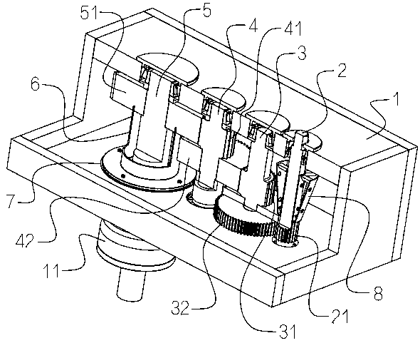
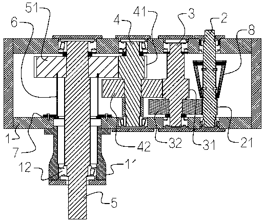
[0034] Embodiment one: if figure 1 and figure 2 As shown, a gear reduction box with upper input and lower output includes a rectangular box 1, and the box 1 is rotatably connected with a first-stage rotating shaft 2, a second-stage rotating shaft 3, and a third-stage rotating shaft 4, all of which are vertically arranged through bearings. Four-stage rotating shaft 5. The upper end of the first-stage rotating shaft 2 protrudes from the upper wall of the box body 1 , and the second-stage rotating shaft 3 and the third-stage rotating shaft 4 are located in the box body 1 . The outer side of the lower wall of the box body 1 is sealed and welded with an output extension sleeve 11, and the lower end of the fourth-stage rotating shaft 5 protrudes from the lower end of the extension sleeve 11. The extension sleeve 11 is provided with a tapered roller bearing 12 for rotationally connecting and supporting the fourth-stage rotating shaft 5. The tapered roller bearing 12 here is prefer...

Embodiment 2

[0045] Embodiment 2: This embodiment is a technical solution obtained through further improvement on the basis of Embodiment 1.

[0046] The difference between this embodiment and Embodiment 1 is that, as Figure 6 , Figure 7 and Figure 8 As shown, the lower end of the three-stage bull gear 51 is also coaxially provided with a second circular groove 512 with a rectangular cross-section, and the second circular groove 512 is outside the first circular groove 511 .

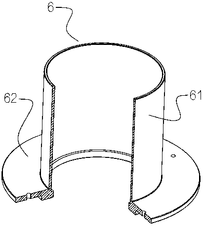
[0047] Such as Figure 6 , Figure 7 , Figure 8 , Figure 9 and Figure 10 As shown, the outer side of the cylindrical side wall 61 is coaxially sleeved with an annular piece 63, and the annular piece 63 is coaxially provided with an annular oil retaining cylinder 64, and the oil retaining cylinder 64 extends into the second annular groove 512 Inside, and there are gaps on the wall surfaces of the oil deflecting cylinder 64 and the second annular groove 512 .

[0048] An annular oil groove 65 is coaxially...


PUM


Abstract

The invention relates to the technical field of drive devices, and discloses an upper input and lower output type speed reduction gear box. The upper input and lower output type speed reduction gear box comprises a box body, wherein the box body forms a three-stage gear speed reduction mechanism through a first-grade rotating shaft, a second-grade rotating shaft, a third-grade rotating shaft, a fourth-grade rotating shaft and gears on the shafts; a three-grade gearwheel is arranged on the fourth-grade rotating shaft; an oil baffle cover, comprising cylindrical sidewalls of which two ends are opened, is fixedly connected into the box body; the cylindrical sidewalls sleeve the outside of the fourth-grade rotating shaft; lower end ports of the cylindrical sidewalls are in sealing connectionwith the inner surface of the lower wall of the box body; a first circular ring slot is formed in the lower end of the third-grade gearwheel; upper end ports of the cylindrical sidewalls extend into the first circular ring slot. According to the upper input and lower output type speed reduction gear box, an oil baffle disc in the prior art is replaced by the improved oil baffle cover; the gear arraignment mode in the scheme enables good oil baffle effect; a bearing at the lower part of the fourth-grade rotating shaft can be lubricated through semi-solid lubricating grease, and thus the risk that liquid lubricating oil leaks from the box body is avoided.

Description

technical field [0001] The invention relates to the technical field of transmission devices, and more specifically relates to a gear reduction box with upper input and lower output. Background technique [0002] In some industrial fields, a gear reduction box with upper input and lower output is often used. The input shaft of this type of gear reduction box is connected to the output shaft of the motor, and the output shaft is used to connect the load. [0003] For example, the inverted umbrella aerator in the field of sewage treatment uses this kind of gear reduction box with input from the top and output from the bottom. The main structure of the inverted umbrella aerator includes motor, coupling, gear reducer and impeller assembly. The input shaft of the gear reduction box and the output shaft of the motor are centered and connected through a coupling, and the impeller assembly is connected to the output shaft of the gear reduction box. [0004] The bearings in this typ...

Claims


Application Information

Patent Timeline
Patent Type & Authority Applications(China)
IPC IPC(8): F16H1/22F16H57/04
CPCF16H1/22F16H57/0412F16H57/0457
Inventor 张萍
Owner 张萍
Why Eureka
Try Eureka