Flanging arrangement for wall hole of thin metal pipe

A technology of metal pipe and outer flanging, which is applied in the field of mechanical processing equipment, can solve the problems of increasing the load of heat pumps, difficulty in improving production efficiency, and unsmooth water flow channels.

Inactive Publication Date: 2006-06-21
杜明干
View PDF0 Cites 13 Cited by
  • Summary
  • Abstract
  • Description
  • Claims
  • Application Information

AI Technical Summary

Problems solved by technology

like Figure 8 As shown, the water flow channel of the main pipe with the inner flanging is not smooth due to the inner flanging, which increases the resistance of the water circulation and increases the load of the heat pump; Figure 7 As shown in the figure, the water flow channel of the mai

Method used


Image

  • Flanging arrangement for wall hole of thin metal pipe
  • Flanging arrangement for wall hole of thin metal pipe
  • Flanging arrangement for wall hole of thin metal pipe

Examples


Embodiment Construction

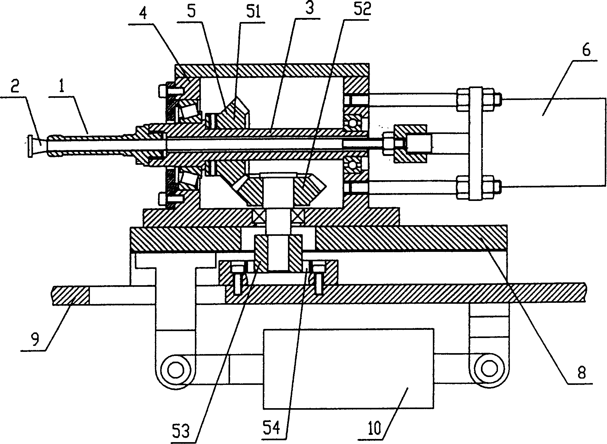
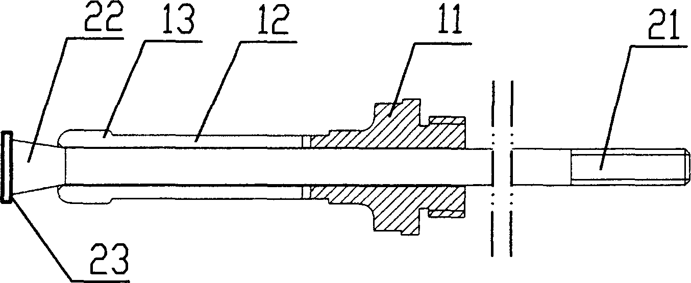
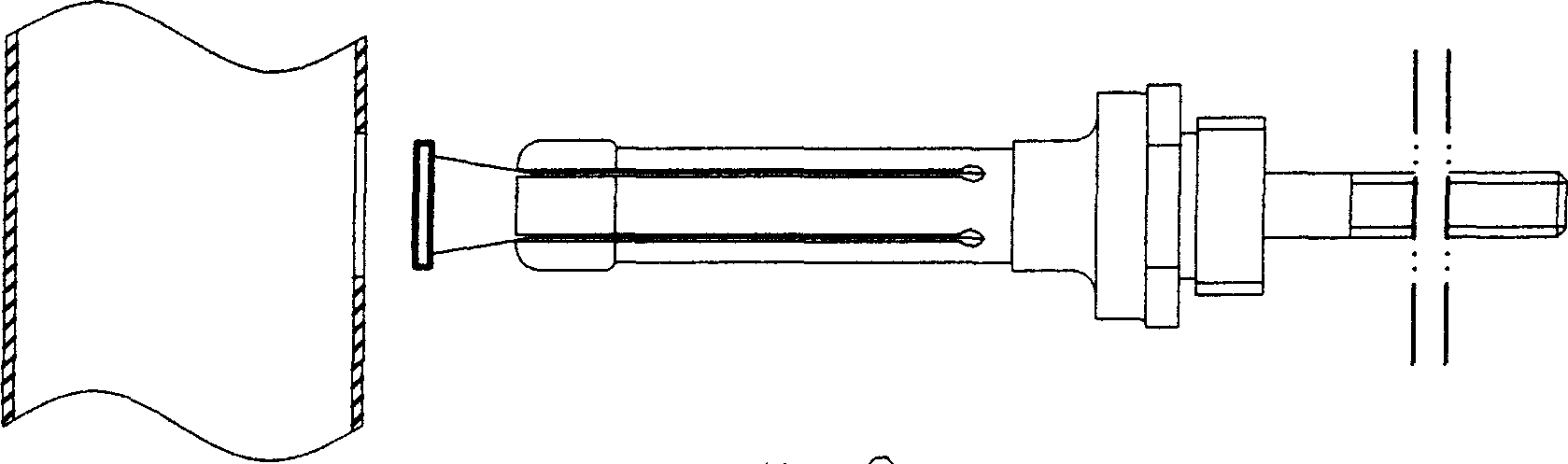
[0015] Such as figure 1 , figure 2 As shown, the flanging device for the wall hole of a thin-walled metal pipe includes a flanging tool 1 and a driving device, wherein:

[0016] The flanging cutter 1 comprises a handle 11, the front end of the handle 11 is provided with a cutter head, the cutter heads are multiple and evenly distributed along the axis of the handle 11, the cutter heads are divided into The elastic portion 12 fixedly connected to the handle 11 and the flanging edge 13 arranged at the end of the elastic portion 12, the outer edge of the flanging edge 13 is located on a common circumference and the diameter of the circumference is smaller than the diameter of the hole to be flanging, said The tool body formed by the handle 11 and some cutter heads is provided with a pull rod hole along the axis, and the pull rod 2 that can open the flanging edge 13 along the elastic part 12 is installed in the pull rod hole. After the flanging edge 13 is opened The outer edge...


PUM


Abstract

The hole outer flanging set for thin wall metal pipe wall includes one cutter and one driving device. The cutter has several cutter bits, which are distributed homogeneously and axially around cutter handle and include an elastic part fixed to the cutter handle and a flanging edge set in the end of the elastic part each; and a cutter body with pull rod capable of expanding the flanging edges along elastic parts inside an axial hole. The flanging edges under the action of the elastic parts are in free state for the cutter head to be inserted into the hole easily. After the cutter head is inserted into the hole, the pull rod is pulled to expand the flanging edges and to form the outer flange before the cutter is rotated and withdrawn. The present invention needs no inner mold, has simple technological process and high work efficiency, and suitable for automatic production.

Description

technical field [0001] The invention relates to a mechanical processing equipment, in particular to a device capable of flanging the wall hole of a thin-walled metal pipe. Background technique [0002] At present, the water chamber of the copper-aluminum composite radiator adopts thin-walled copper tubes. During the processing, it is necessary to process many holes for connecting gas or liquid on the copper tubes, and weld connecting tubes between the holes opposite to the two main pipes. for heat exchange. In order to improve the welding strength, it is required to turn the edge of the hole inward or outward. Such as Figure 8 As shown, the water flow channel of the main pipe with the inner flanging is not smooth due to the inner flanging, which increases the resistance of the water circulation and increases the load of the heat pump; Figure 7 As shown in Fig. 1, the water flow channel of the main pipe with flanging is relatively smooth, but the flanging process is relat...

Claims


Application Information

Patent Timeline
IPC IPC(8): B21D19/12
Inventor 杜明乾
Owner 杜明干
Why Eureka
Try Eureka