
Piping structure for transporting a fuel, resin tube for transporting fuel in the piping structure and producing method thereof

A technology of resin pipes and pipes, applied in the direction of pipes/pipe joints/pipe fittings, the arrangement combined with the fuel supply of internal combustion engines, pipe supports, etc., which can solve the problems of large vibration of resin pipes

Inactive Publication Date: 2006-06-21
SUMITOMO RIKO CO LTD
View PDF4 Cites 13 Cited by
  • Summary
  • Abstract
  • Description
  • Claims
  • Application Information

AI Technical Summary

Problems solved by technology

However, especially in a two-wheeled motor vehicle in which the engine heaves together with the rear wheels (for example, disclosed in Patent Documents 6 and 7 below), since the resin pipe equipped with the connector is subjected to greater vibration and the resin pipe vibrates Larger, so prone to the above problems

Method used


Image

  • Piping structure for transporting a fuel, resin tube for transporting fuel in the piping structure and producing method thereof
  • Piping structure for transporting a fuel, resin tube for transporting fuel in the piping structure and producing method thereof
  • Piping structure for transporting a fuel, resin tube for transporting fuel in the piping structure and producing method thereof

Examples


Embodiment Construction

[0139] Referring to Figures 2 and 3, reference numeral 10 is a mating duct 10 integrally formed with a component part such as an engine or a fuel tank firmly fixed to the vehicle body. The fitting pipe 10 is formed with an engaging projection (pipe-side engaging portion) 12 projecting annularly on its outer peripheral surface and around it.

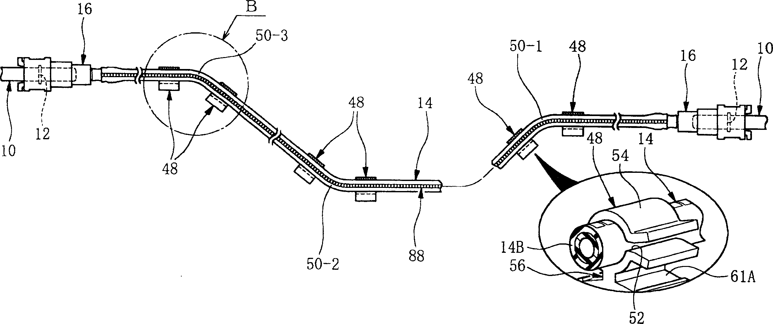
[0140] Fig. 4 shows the state of the connector-equipped resin pipe between the engine and the fuel tank even before it is assembled in the body of the motor vehicle. In these figures, reference numeral 14 denotes a resin tube, and reference numeral 16 denotes a connector (quick connector). These connectors 16 , 16 are mounted on both ends of the resin pipe 14 . However, when the resin tube 14 is directly connected to a fitting member such as the fitting pipe 10 on one end of the resin tube by press fitting or the like, the connector 16 is only mounted on the other end of the resin tube 14 .

[0141]Here, the resin pipe 14 has a straight...


PUM


Abstract

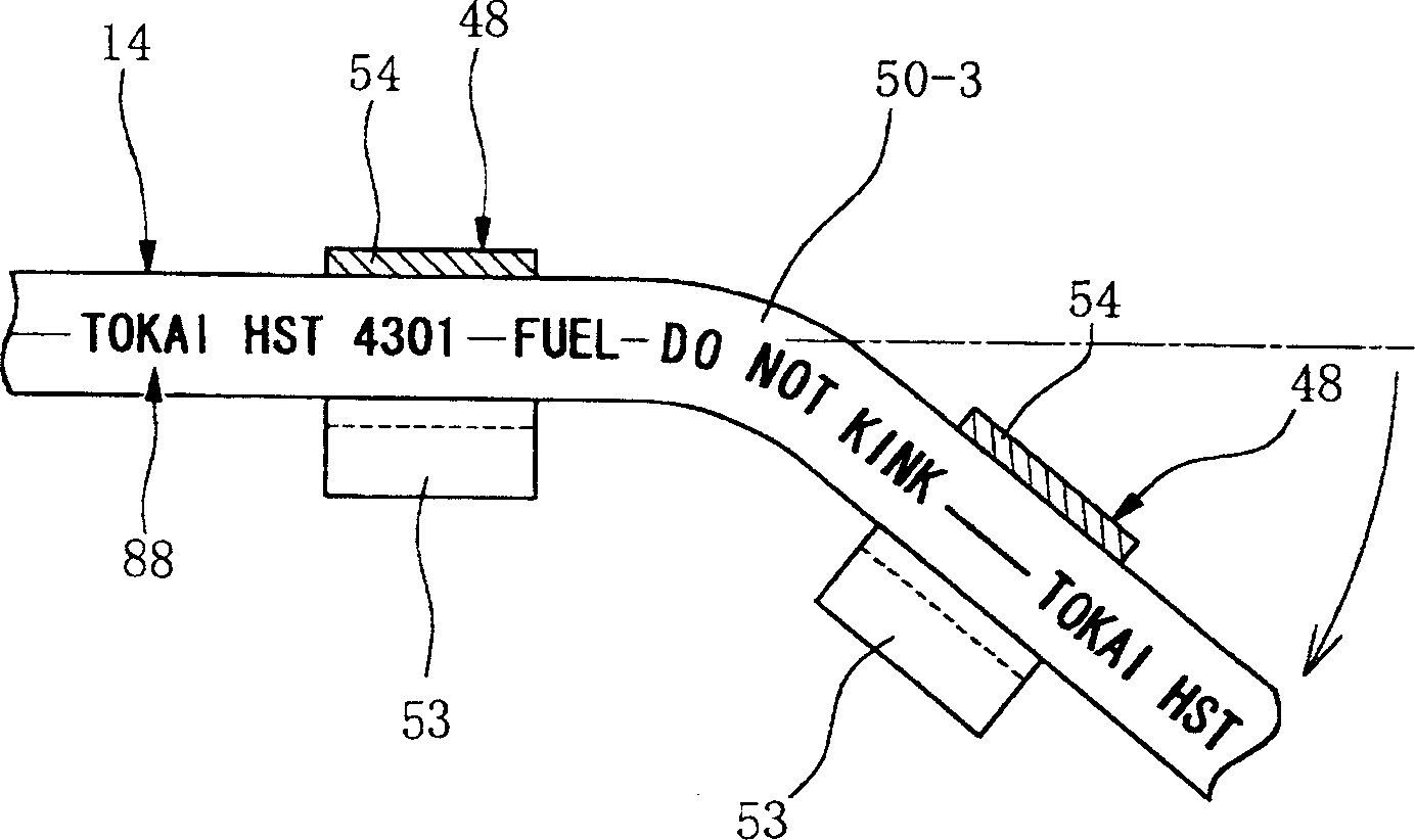
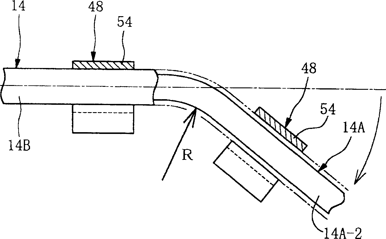
The present invention provides a reliable and inexpensive pipeline structure for transporting fuel. A piping structure for delivering fuel arranged between an engine and a fuel tank is composed of a resin pipe (14) formed into a straight pipe shape. The resin tube (14) is bent at one or more positions along the longitudinal direction of the resin tube (14) to form one or more bent portions (50-1, 50-2, 50-3), whereby its have a predetermined curved shape. The resin tube (14) is fixed in the vehicle body to hold the bent portions (50-1, 50-2, 50-3), thereby being assembled in the vehicle body.

Description

technical field [0001] The present invention relates to a pipe structure for conveying fuel, a resin pipe for conveying fuel suitable in the pipe structure, and a method for producing the resin pipe. Background technique [0002] Resin pipes have previously been used to transport fuel, for example from a fuel tank to an engine. [0003] The resin pipe is connected with a mating pipe on the vehicle body side to constitute a pipe system for conveying fuel. [0004] Conventionally, in order to connect the resin pipe to the mating pipe, a connector (quick connector) has been used which allows easy and quick connection to the mating pipe. [0005] Such a connector is disclosed, for example, in Patent Document 1 below. 12 and 13 show an example of a concrete structure of a connector. [0006] In Figs. 12 and 13, reference numeral 200 denotes a resin tube. Reference numeral 202 denotes a fitting pipe to be connected with the resin pipe 200 . [0007] The fitting pipe 202 is fo...

Claims


Application Information

Patent Timeline
Patent Type & Authority Applications(China)
IPC IPC(8): B62J37/00B60K15/01F16L3/08F16L11/04F16L37/08
Inventor 井上知己笹川雅之
Owner SUMITOMO RIKO CO LTD
Learn More