Unit for determining broken end position of weaving machine

A technology for determining device and warp breaking, applied in looms, weaving, textiles and papermaking, etc., can solve problems such as difficult to find the position of warp breaking, and achieve the effect of improving weaving efficiency

Inactive Publication Date: 2006-06-21
FOSHAN ZHONGFANGLIAN INSPECTION TECH SERVICE CO LTD
View PDF0 Cites 1 Cited by
  • Summary
  • Abstract
  • Description
  • Claims
  • Application Information

AI Technical Summary

Problems solved by technology

[0003] The purpose of the present invention is to solve the problem that it is difficult to find the position of the warp break after the warp is broken during weaving, and to provide a device for determining the position of the warp break of the loom that is accurate in finding the position of the warp break, saves time, and improves the production efficiency of the loom

Method used


Image

  • Unit for determining broken end position of weaving machine
  • Unit for determining broken end position of weaving machine

Examples


Embodiment Construction

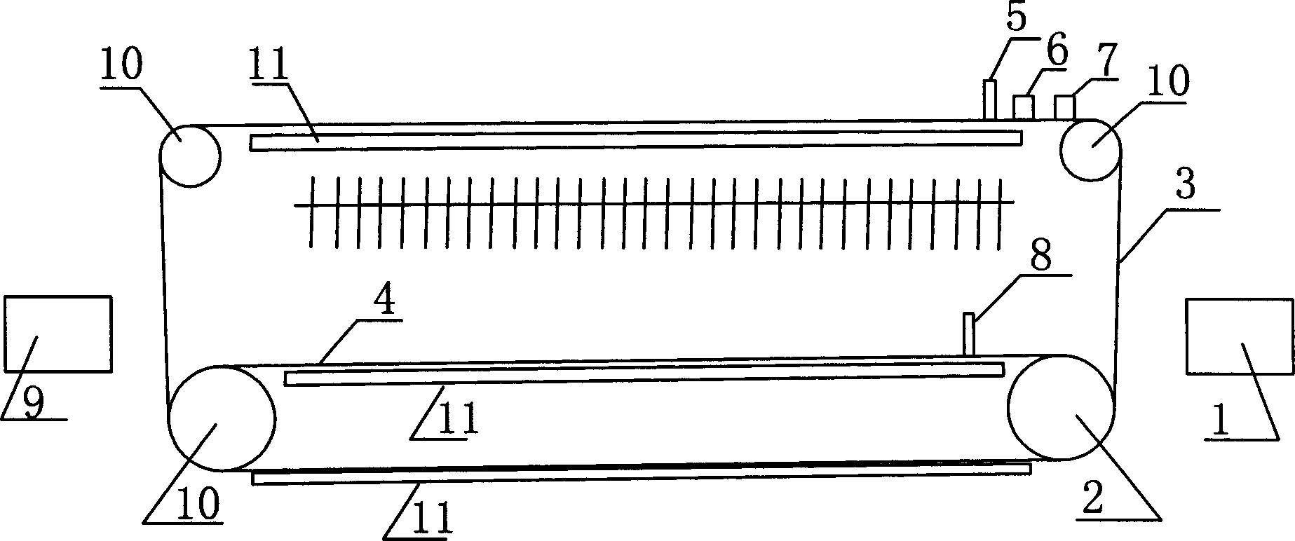
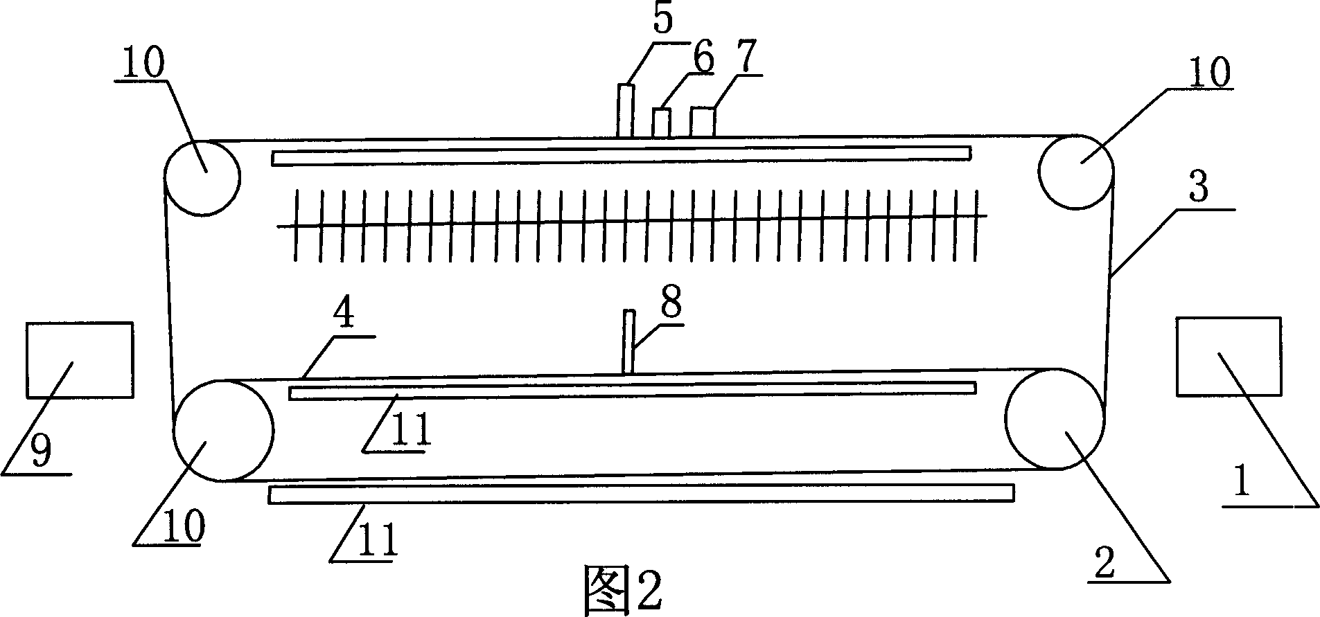
[0008] Loom warp breaking position determining device such as figure 1 As shown, it consists of distribution box 1, small motor 2, toothed belt A3, toothed belt B4, indicator light 5, switch button 6, contact sensor A7, contact sensor B8, photoelectric sensor 9, guide roller 10, guide rail 11 . Among them, the small motor 2, the indicator light 5, the switch button 6, the contact sensor A7, the contact sensor B8, and the photoelectric sensor 9 are all connected to the distribution box 1 by wires; the indicator light 5, the switch button 6, and the contact sensor A7 are all in the gear On the belt A3, the position is as shown in the figure; the contact sensor B8 is on the toothed belt B4. The 2 wheels of the small motor are toothed wheels, and the toothed belt A3 and the toothed belt B4 are non-extensible plastic belts. The toothed belt A3 and the toothed belt B4 bypass the guide roller 10 and run on the guide rail 11, and the distance between the contact sensor B8 and the dr...


PUM


Abstract

The invention discloses a unit for defining the broken warp location. The unit comprises micro-machine, synchronization teeth type belt A, synchronization teeth type belt B, contact pick up A, contact pick up B, guiding light, switching push-button, photoelectric sensing device, teeth type belt guide rail and teeth type belt guide roller. The teeth type belt A and teeth type belt B are enclosed type belt. The teeth type belt A and teeth type belt B depends on generator to move. The guiding light, switching push-button and contact pick up A are settled on teeth type belt A and contact pick up B is settled on teeth type belt B. The contact pick up A, contact pick up B, guiding light, switching push-button, photoelectric sensing device and micro-machine are connected with electric switch box by wire. The teeth type belt A and teeth type belt B operate on the guide rail beyond the guide roller. The device can be exchanged on the loom, and the width is according to the width of loom. The teeth type belt A and teeth type belt B are no extension plastics belt.

Description

Technical field: [0001] The invention is an auxiliary device capable of accurately determining the position of warp breakage of a loom and improving the weaving efficiency of a weaving loom. technical background: [0002] Existing loom broken warp parking is all realized by warp stopper, when loom breaks warp, warp stopper falls and makes loom stop by mechanical device or photoelectric induction device makes loom stop. But the specific position of the broken warp still will be searched by the weaving stopper tool body. When weaving low-count yarns and small warp density fabrics, it is convenient to find the warp break position. When weaving fabrics with high yarn count and high warp density, especially high-count and high-density wide-width fabrics, it is particularly difficult for the operator to find the position of the broken warp, which delays a lot of time, affects weaving efficiency, and increases the labor intensity of workers. By using the device, the swing device ...

Claims


Application Information

Patent Timeline
Patent Type & Authority Applications(China)
IPC IPC(8): D03D51/20
Inventor 苗赫然王静贺显伟
Owner FOSHAN ZHONGFANGLIAN INSPECTION TECH SERVICE CO LTD
Why Eureka
Try Eureka