
Horizontal knitting machine

A technology of flat knitting machine and head, applied in the direction of weft knitting, knitting, textile and paper making, etc., can solve the problems of high energy consumption, affecting the economic benefits of enterprises, and low transmission efficiency.

Inactive Publication Date: 2019-04-05
ZHEJIANG RUIFENG INTELLIGENT TECH CO LTD
View PDF15 Cites 10 Cited by
  • Summary
  • Abstract
  • Description
  • Claims
  • Application Information

AI Technical Summary

Problems solved by technology

[0002] In the existing flat knitting machine, the transmission mechanism usually uses one motor to drive multiple functional components to realize the knitting of gloves, socks and other items. Because it uses multi-ring mechanical transmission, its transmission parts and components are numerous and complex in structure. The large size leads to excessive energy consumption, greatly increased production costs, and problems such as low transmission efficiency, slow weaving speed, and difficult maintenance and debugging during the use of the machine, which greatly affect the economic benefits of the enterprise.

Method used


Image

  • Horizontal knitting machine
  • Horizontal knitting machine
  • Horizontal knitting machine

Examples


Embodiment Construction

[0038] The present invention can be explained in more detail through the following embodiments:

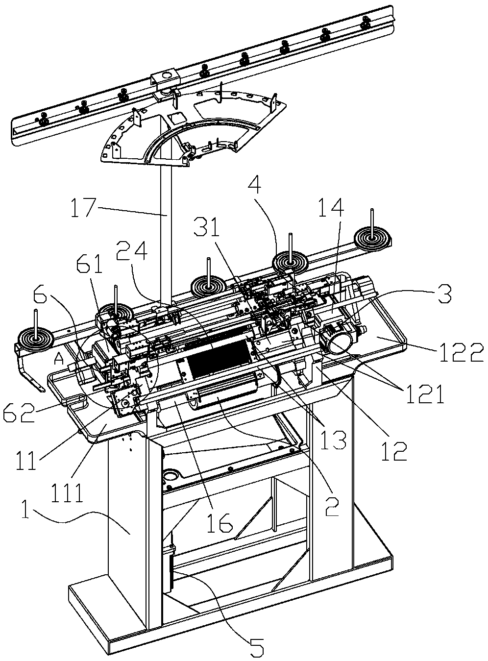
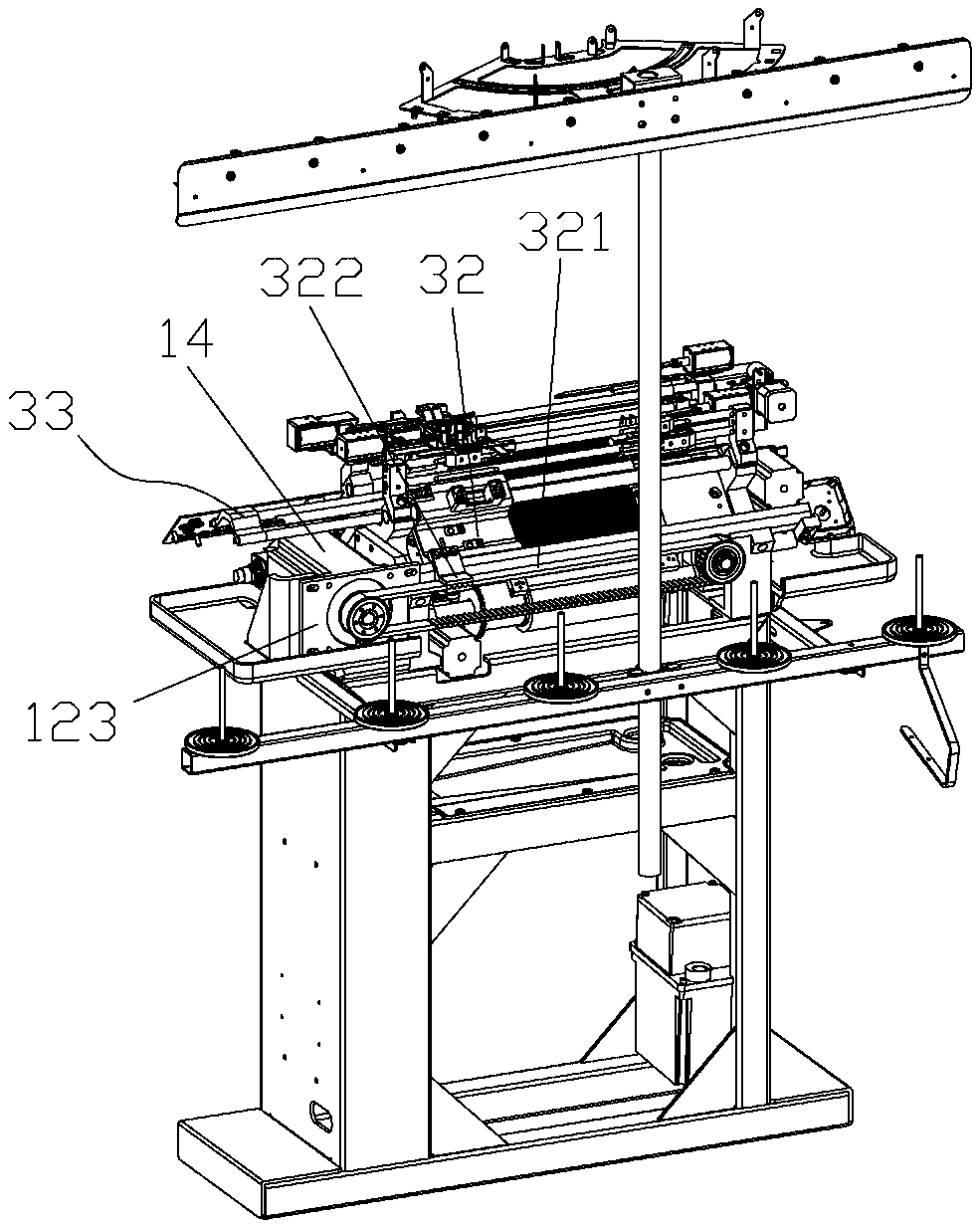
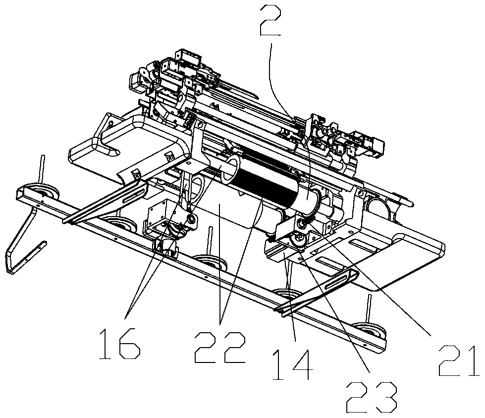
[0039] Such as figure 1 , 2 A flat knitting machine shown includes a main frame 1, a left base 11 and a right base 12 are arranged on the main frame 1, and a needle selection system 2 is arranged between the left base 11 and the right base 12. The top of the system 2 is provided with a slide rail assembly 13, the slide rail assembly 13 is installed on the left base 11 and the right base 12, the slide rail assembly 13 is provided with a machine head part 3, and the machine head part 3 includes a front machine head assembly 31 With the rear nose assembly 32, the front nose assembly 31 and the rear nose assembly 32 are arranged symmetrically or asymmetrically before and after, and the right side lower end of the right base 12 is provided with a motor seat 122, combining Figure 12 , the front side of the motor base 122 is provided with a control operation panel 124, the motor base ...


PUM


Abstract

The invention mainly relates to a horizontal knitting machine. The horizontal knitting machine comprises a main rack, a needle selection system, a sliding rail assembly, a machine head part, a shuttlepart, a yarn cutting device and a finger splitting system, wherein the needle selection system comprises a roller mechanism, two rollers of the roller mechanism are driven by an independent driving device, the sliding rail assembly is arranged above the needle selection system, the machine head part is arranged on the sliding rail assembly, the machine head part comprises a front machine head assembly and a rear machine head assembly, the driving device is in linkage connection with the front machine head assembly and the rear machine head assembly through a transmission assembly, so that thefront machine head assembly and the rear machine head assembly achieve horizontal reciprocating motion on the sliding rail assembly, the upper end of the machine head part is provided with a shuttleassembly, the shuttle assembly is intermittently driven by the machine head part, the yarn cutting device is connected with the independent driving device for driving, and the finger splitting systemcomprises a fork knife part and a scissors part. The horizontal knitting machine has the advantages that the structure is simple, the horizontal knitting machine is portable and flexible, the operating load is low, the energy consumption is low, the transmission and weaving efficiency is improved, and the maintenance and debugging are convenient, and economic benefits of enterprises is increased.

Description

technical field [0001] The invention relates to a flat knitting machine, which belongs to the technical field of knitting machinery. Background technique [0002] In the existing flat knitting machine, the transmission mechanism usually uses one motor to drive multiple functional components to realize the knitting of gloves, socks and other items. Because it uses multi-ring mechanical transmission, its transmission parts and components are numerous and complex in structure. The large size leads to excessive energy consumption, greatly increased production costs, and problems such as low transmission efficiency, slow weaving speed, and difficult maintenance and debugging during the use of the machine, which greatly affect the economic benefits of the enterprise. Contents of the invention [0003] In order to solve the above problems, the present invention provides a flat knitting machine, the design structure is simpler, light and flexible, the operating load is light, the ...

Claims


Application Information

Patent Timeline
Patent Type & Authority Applications(China)
IPC IPC(8): D04B15/70
CPCD04B15/70D04B15/36D04B15/565D04B15/22D04B15/96
Inventor 兰永亮
Owner ZHEJIANG RUIFENG INTELLIGENT TECH CO LTD
Learn More