Smoke exhaust ventilator

A range hood and impeller technology, applied in the field of range hoods, can solve the problems of stained windows and external walls, unhygienic appearance, and reduced exhaust efficiency, and achieve easy collection and discharge, high power, and exhaust efficiency high effect

Inactive Publication Date: 2006-06-21
杨超敏
View PDF0 Cites 2 Cited by
  • Summary
  • Abstract
  • Description
  • Claims
  • Application Information

AI Technical Summary

Problems solved by technology

But this structure has no effect on the oil and water that has been thrown into the surrounding space and the large amount of oil and water separated by the protective door, fan head, and air flow channel. Due to poor drainage, a large amount of oil and water still accumulates at the bottom of the air flow channel. Let the oil and water flow freely, so that the oil drips on the window or the outer wall, making the window and the outer wall stained, which is very unhygienic and unsightly
[0005] 3. Because there is a certain gap between the intake end panel and the impeller, this gap is distributed at the intake end around the impeller, which will generate a local negative pressure and form backflow, which will reduce the exhaust efficiency

Method used


Image

  • Smoke exhaust ventilator
  • Smoke exhaust ventilator
  • Smoke exhaust ventilator

Examples


Embodiment approach 1

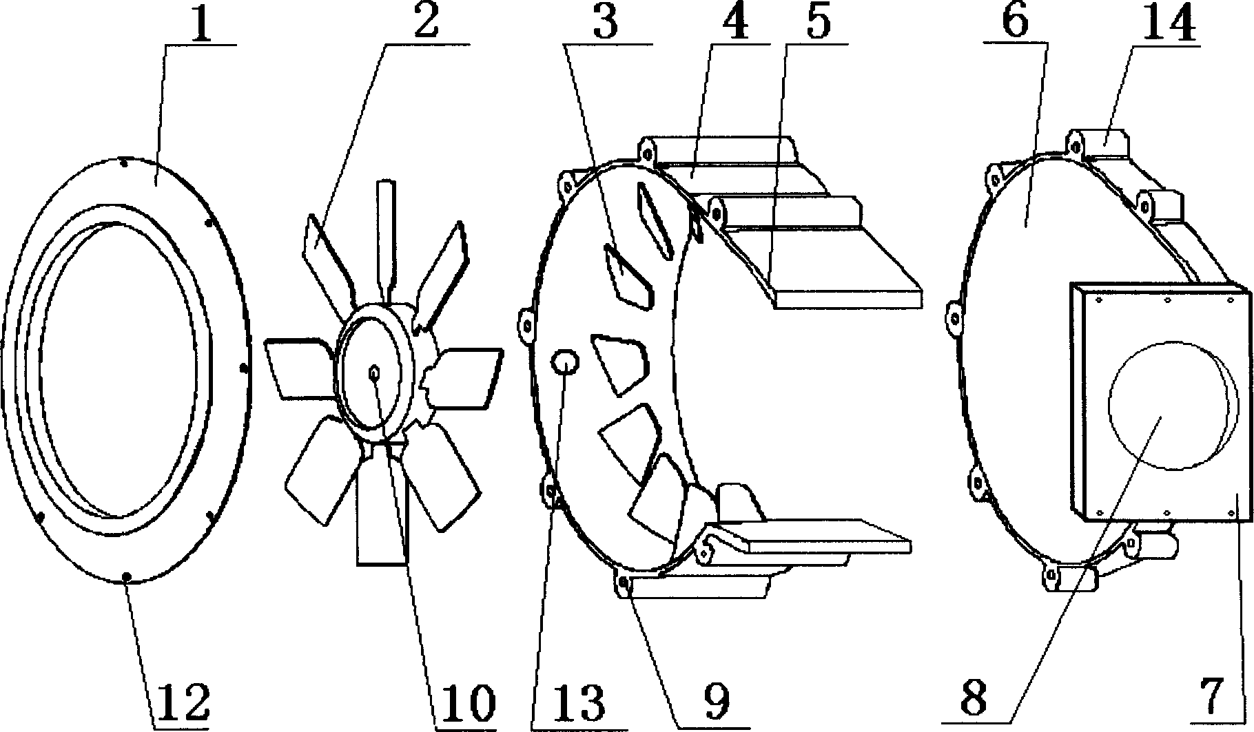
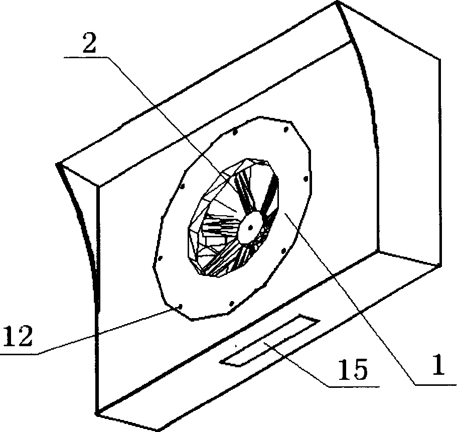
[0016] Embodiment 1: The plane where the impeller is located is perpendicular to the ground, which is called the side suction type, and its exhaust port faces upwards, and then it is led out of the room with a pipe. Side suction such as figure 1 , figure 2 , Figure 4 , the impeller 2 is placed in the air drum 4, one end of the impeller 2 in the axial direction is the panel 1, the other end is the deflector 3, the exhaust port 8 is arranged in the circumferential direction of the impeller 2, and the oil outlet 13 is arranged at the bottom of the air drum 4 . The guide vanes 3 are distributed at intervals on the inside of the wind drum and in a circular plane parallel to the impeller, and the angle between it and the circumferential line is 22 degrees; there is an exhaust passage 5 between the exhaust port 8 and the impeller 2; the panel 1 There is a windshield ring 11 inboard of the air inlet.

[0017] Panel 1, air drum 4, exhaust aisle 5, and front baffle 6 form a closed...

Embodiment approach 2

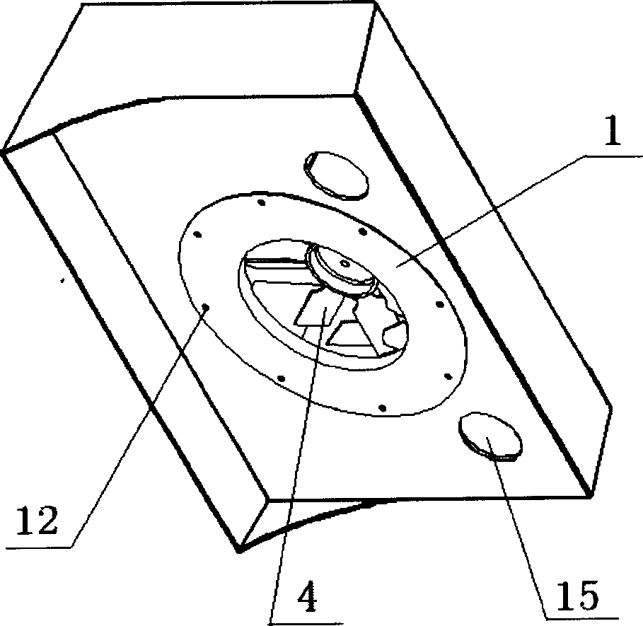
[0022] Embodiment 2: If the plane where the impeller 2 is located is parallel to the ground, it is called a top suction type, and its exhaust port is led out of the room through the wall or window forward. The oil outlet 13 is located at the plane where the panel is located, and the oil and water can be caught with the oil box 15 again. The deflectors 3 are distributed on the inner wall of the wind drum 4 at intervals and in a circular plane parallel to the impeller, the angle between the blades of the impeller 2 and the circumference is 18 degrees, and the angle between the blades of the impeller 2 and the circumference is 28 degrees. Windshield ring 11 adopts Figure 5 "L" shape shown. Except for the parameters in Table 1, the rest are the same as Embodiment 1.

Embodiment approach 3

[0023] Embodiment 3: The deflectors 3 are distributed at intervals on the inner side of the wind drum and in a circular plane parallel to the impeller, the angle between it and the circumference line is 30 degrees, and the angle between the blades of the impeller 2 and the circumference line is 50 degrees Spend. Windshield ring 11 adopts Figure 6 "I" shape shown. The rest are the same as Embodiment 2.


PUM


Abstract

This invention relates to one smoke exhaust ventilator with large power and green effect, which comprises the following technique points: The gas is absorbed from turbine shaft and is exhausted from the outside of the shaft; the turbine shaft is put inside wind bump with one end as panel and the other as flow guiding slice; the exhaust mouth is located around the circle; the oil exhaust mouth is located on the wind bump and panel formed space bottom. The invention mainly is used to remove the waste gas from production, experiment and cooking.

Description

technical field [0001] The invention relates to a range hood, in particular to an energy-saving and environment-friendly range hood. Background technique [0002] At present, in order to get rid of production, testing, cooking and combustion waste gas, exhaust fans are widely used, which greatly improves the indoor air and kitchen environment sanitation. However, ordinary range hoods and exhaust fans have the following disadvantages: [0003] 1. Most of them adopt the method of axial air intake and axial exhaust. The angle between the fan blade and the circumferential line is small, and the exhaust efficiency is not high. [0004] 2. When the oil and water pass through the high-speed rotating impeller, a large amount of oil and water are separated from the flue gas, and are thrown by the impeller to the air inlet panel and the surrounding space. In addition, the oil fume scours the fan head and the surface of the air flow channel , also produces the separation and adhesion...

Claims


Application Information

Patent Timeline
Patent Type & Authority Applications(China)
IPC IPC(8): F24C15/20
Inventor 杨超敏
Owner 杨超敏
Why Eureka
Try Eureka