Method for processing spiral bevel gear and apparatus for forming large wheel of bevel gear thereof

A technology of spiral bevel gear and processing method, which is applied to components with teeth, belts/chains/gears, gear teeth, etc., which can solve problems such as difficult adjustments and affecting the processing accuracy of gears, and achieve high precision effects

Inactive Publication Date: 2006-06-28
潘旭华
View PDF0 Cites 12 Cited by
  • Summary
  • Abstract
  • Description
  • Claims
  • Application Information

AI Technical Summary

Problems solved by technology

[0002] In the existing gear manufacturing, the spiral bevel gear is often processed by the semi-hobbing method, that is, the large wheel is cut out by the forming method, and the surfaces on both sides of the pinion teeth are cut out by the generating method. The spiral processed by this method During the adjustment process of bevel gea

Method used


Image

  • Method for processing spiral bevel gear and apparatus for forming large wheel of bevel gear thereof
  • Method for processing spiral bevel gear and apparatus for forming large wheel of bevel gear thereof

Examples


Embodiment Construction

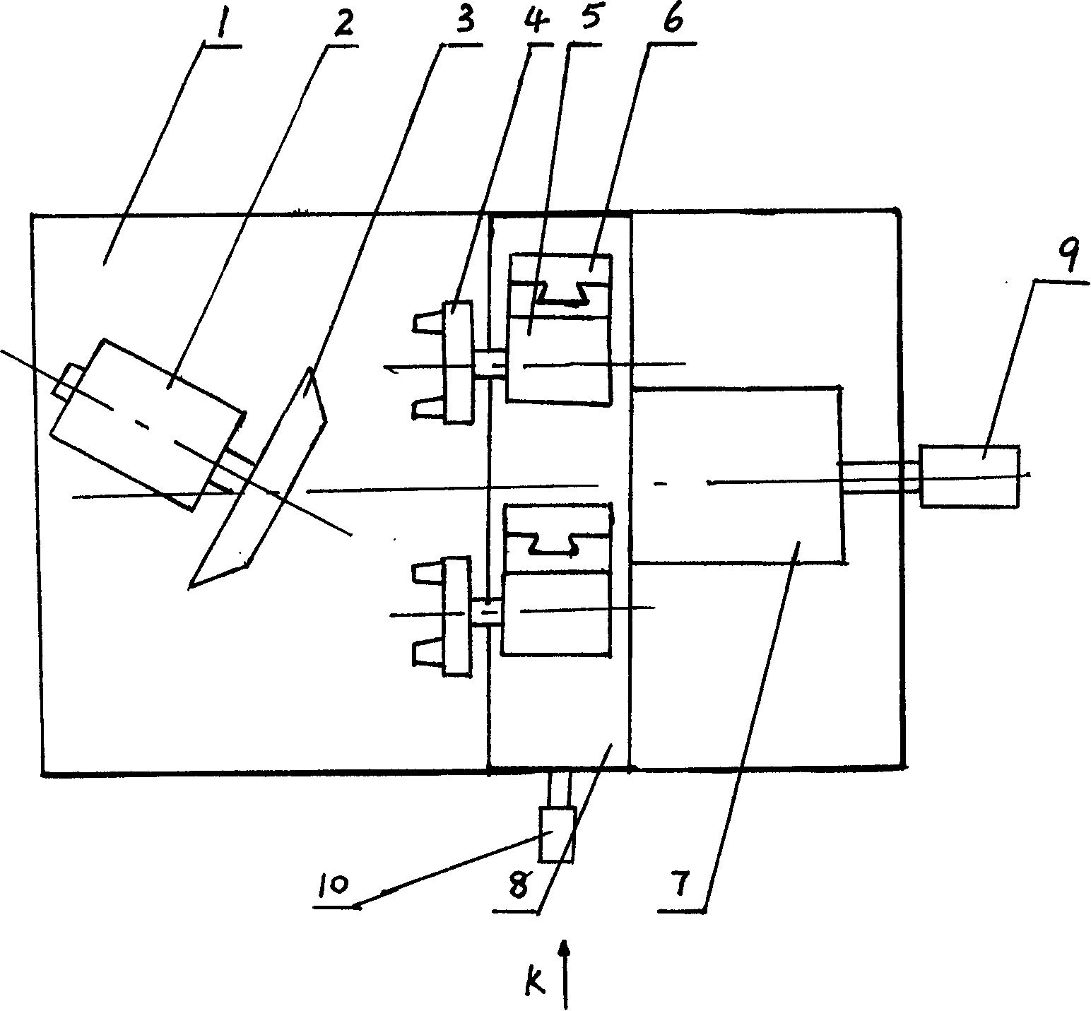
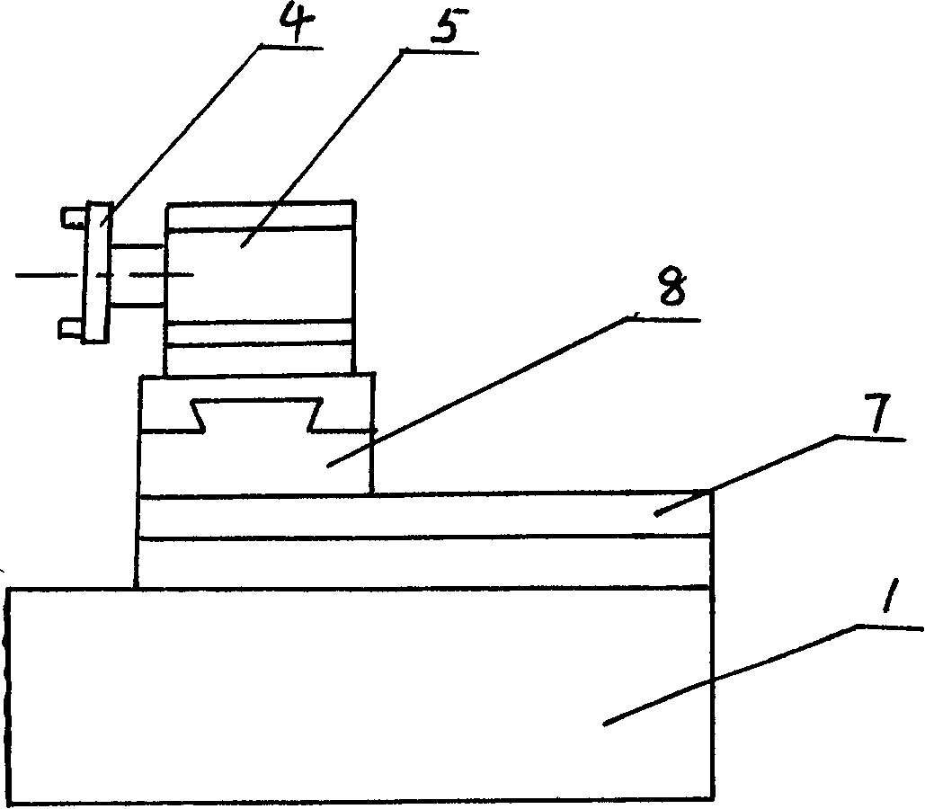
[0012] A processing method for a spiral bevel gear, characterized in that: a half hobbing method is adopted, wherein the surface of both sides of the teeth of the small wheel is cut out by the generating method, the big wheel is cut out by the forming method, and the tooth profile of the concave and convex surface of the big wheel is processed Different shapes of cutterheads are used for forming respectively. First, the shape of each formed cutterhead is adjusted and modified according to the requirements of the contact area in the height direction, and then the modified cutterheads are installed on the respective cutterhead axes of the same machine tool. Each cutter head is adjusted by its own vertical guide rail, and its movement is controlled by a common transverse guide rail and feed guide rail, and different cutter heads are used to process the concave and convex surfaces of the large wheel.

[0013] Such as figure 1 , 2 As shown, a bevel gear wheel forming device includ...


PUM


Abstract

A method for manufacturing the spiral bevel gear is characterized by that a semi-hobbing method is used, the teeth of small gear are made by generation method, and the big gear is made by shaping method. The concave-convex surface of big gear is shaped by multiple cutterheads with different shapes. Each cutter head has own axle and holder installed on own vertical track. All cutter heads have common transverse track and feeding track and are controlled by numerally controlled motor.

Description

technical field [0001] The invention belongs to the category of gear manufacturing, in particular to a processing method of a spiral bevel gear and a large wheel forming device for the bevel gear. Background technique [0002] In the existing gear manufacturing, the spiral bevel gear is often processed by the semi-hobbing method, that is, the large wheel is cut out by the forming method, and the surfaces on both sides of the pinion teeth are cut out by the generating method. The spiral processed by this method During the adjustment process of bevel gears, the biggest difficulty is to adjust the contact between the two wheels in the direction of tooth height (that is, the width of the contact area). Difficulty, especially when the width and length of the contact area are required to be more than 60%, the adjustment becomes more difficult, thereby affecting the machining accuracy of the gear. Contents of the invention [0003] The purpose of the present invention is to addr...

Claims


Application Information

Patent Timeline
IPC IPC(8): B23F9/00B23F5/00
Inventor 潘旭华
Owner 潘旭华
Why Eureka
Try Eureka