
Infrared ray gas analyzer using photon crystal optical fiber as gas chamber

A technology of photonic crystal fiber and gas analyzer, which is applied in the direction of material analysis, analysis materials, instruments, etc. through optical means, can solve the problems of large volume and bulkiness of infrared gas analyzer, and achieve light weight, high measurement accuracy, The effect of improving performance

Inactive Publication Date: 2006-06-28
HANGZHOU DIANZI UNIV
View PDF7 Cites 8 Cited by
  • Summary
  • Abstract
  • Description
  • Claims
  • Application Information

AI Technical Summary

Problems solved by technology

Therefore, the gas chamber needs to have a certain propagation length to generate sufficient light loss, which makes the infrared gas analyzer bulky and heavy, and requires alignment adjustment of the light emitting unit and receiving unit, which also has a negative impact on the maintenance of the analyzer. important question

Method used


Image

  • Infrared ray gas analyzer using photon crystal optical fiber as gas chamber

Examples


Embodiment Construction

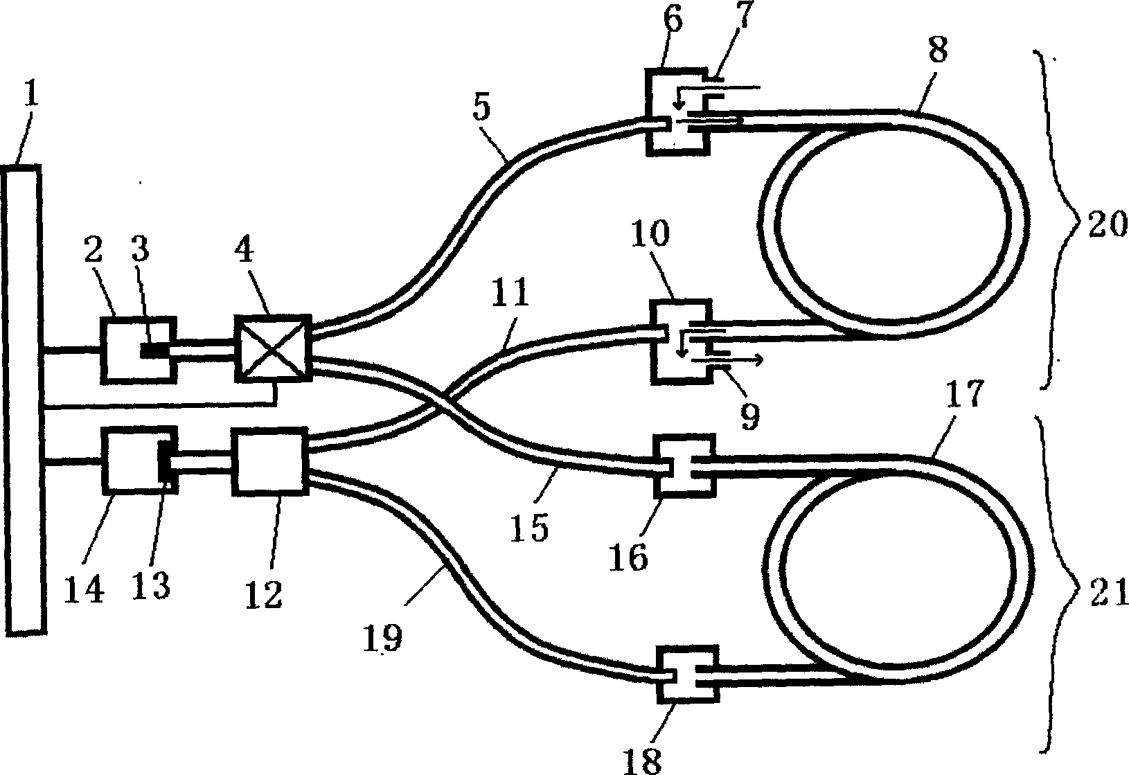
[0014] Such as figure 1 As shown, the gas concentration detection device includes a measurement path 20 and a reference path 21 .

[0015] Among them, one end of the measurement path photonic crystal fiber 8 in the measurement path 20 is connected to the inlet connection unit 6 and communicates with the inlet connection unit 6 , and the other end is connected to and communicates with the outlet connection unit 10 . The air intake connection unit 6 is hollow and is provided with an air intake 7 . The air outlet connection unit 10 is hollow and is provided with an air outlet 9 . The gas to be measured can pass into the photonic crystal fiber 8 of the measurement path through the air inlet 7, and be discharged through the gas outlet 9 through the photonic crystal fiber 8 of the measurement path, so that the photonic crystal fiber 8 of the measurement path is filled with the gas to be measured. One end of the measurement path input optical fiber 5 is connected to the intake conn...


PUM


Abstract

An infrared gas analyzer using photon crystal optical fiber as gas chamber consists of measuring path and reference path .It features that character of constraining transmission light by photon crystal optical fiber and character of its core layer being hollow are utilized separately to use hollow layer of photon crystal optical fiber directly as gas chamber to carry out measurement on reference gas and gas to be tested.

Description

technical field [0001] The invention relates to an infrared gas concentration detection device, in particular to an infrared gas analyzer using a photonic crystal fiber as a gas chamber. Background technique [0002] Infrared gas analyzers use the principle of absorption spectroscopy that light energy is absorbed by gas molecules at specific frequencies to measure the concentration of gases. The infrared gas analyzer consists of a light emitting unit, a gas chamber, a light receiving unit, a data processing unit and other auxiliary units. The light emitting unit includes various infrared light sources, and the infrared light emitted by it enters the gas chamber, is absorbed and attenuated by the gas in the gas chamber, and then irradiates the receiving unit. The receiving unit generally includes an infrared detector, which converts the variation of absorption and attenuation of infrared light into a variation of an electrical signal. After the electrical signal is processed...

Claims


Application Information

Patent Timeline
Patent Type & Authority Applications(China)
IPC IPC(8): G01N21/01G01N21/3504
Inventor 卢山鹰
Owner HANGZHOU DIANZI UNIV
Learn More