Full automatic subassembly of lock bolt

A fully automatic technology for anti-loosening bolts, applied in the direction of bolts, threaded fasteners, screws, etc., can solve the problems of reducing the strength of bolts and nuts, inconvenient disassembly and maintenance, complicated processes, etc., and achieves convenient processing and use, simple structure, Good effect of anti-loosening performance

Inactive Publication Date: 2006-07-05
赖起兵
View PDF0 Cites 13 Cited by
  • Summary
  • Abstract
  • Description
  • Claims
  • Application Information

AI Technical Summary

Problems solved by technology

However, due to the simultaneous processing of right and left threads with different diameters on the bolts, not only the process is complicated, but als

Method used


Image

  • Full automatic subassembly of lock bolt
  • Full automatic subassembly of lock bolt
  • Full automatic subassembly of lock bolt

Examples


Embodiment Construction

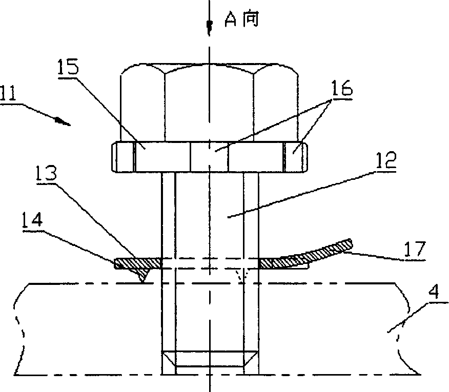
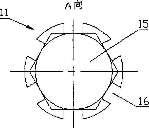
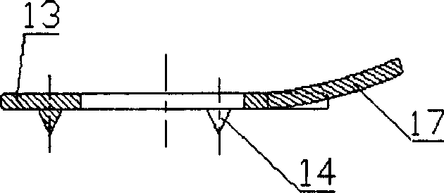
[0022] Embodiments of the present invention are as Figure 1-Figure 4 As shown, it includes a bolt 11 and a washer 13 sleeved on the periphery of the screw rod 12 of the bolt. It is characterized in that: the front side of the washer has tines 14 for fastening the supporting surface of the connected part, and the rear peripheral part of the washer A positioning piece 17 is provided on the top for fastening the channel 16 provided on the outer peripheral wall of the nut 15 of the bolt. The above-mentioned locating elements are elastic locating elements distributed on the radial periphery of the rear side of the washer and can be bent backwards.

[0023] When in use, when the bolt is tightened, first press the tines on the front side of the washer into the supporting surface of the connected part, so that the washer is fastened on the connected part; when the bolt continues to rotate until one of the elastic positioning parts corresponds to the outer circumference of the nut Wh...


PUM


Abstract

A lock bolt component consists of bolt and gasket sheathed on periphery of bolt screw. It features that sharp tooth to lock with bearing surface of connected piece is set on front side of gasket and positioning element to lock with slot nut external peripheral wall of bolt is set on back side gasket periphery.

Description

technical field [0001] The invention relates to a fully automatic anti-loosening bolt assembly used for mounting and connecting parts. Background technique [0002] At present, most of the fasteners used in parts assembly are bolts and nuts. In order to prevent the bolts and nuts from loosening, a spring washer is usually added between the bolt and the part or between the nut and the part, so that the spring washer can prevent loosening. Since the two joints of the spring washer have sharp angles and are flared outward, when the bolt or nut is loosened, the two joints of the spring washer can withstand the bolt (nut) and parts so as to achieve the anti-loosening effect. However, in the environment of vibration or rotation, it is found that the bolts and nuts are often loosened, which brings adverse consequences to the equipment. [0003] In order to overcome the problem of loose bolts and nuts, a lock nut disclosed in Patent No. 98233737 discloses the following technical s...

Claims


Application Information

Patent Timeline
IPC IPC(8): F16B39/24F16B43/00
CPCF16B39/108
Inventor 赖起兵
Owner 赖起兵
Why Eureka
Try Eureka