Method and apparatus for cooling extruded soft tube made of plastic film

A technology of film hose and plastic film, applied in the field of tubular plastic film, can solve problems such as obstacles to increase production

Inactive Publication Date: 2006-07-05
DR-派克Ⅱ有限公司
View PDF1 Cites 3 Cited by
  • Summary
  • Abstract
  • Description
  • Claims
  • Application Information

AI Technical Summary

Problems solved by technology

As mentioned above, for conventional cooling techniques, the maximum usable film velocity is about 120m / min, which is an obstacle to further increase the throughput

Method used


Image

  • Method and apparatus for cooling extruded soft tube made of plastic film
  • Method and apparatus for cooling extruded soft tube made of plastic film
  • Method and apparatus for cooling extruded soft tube made of plastic film

Examples


Embodiment Construction

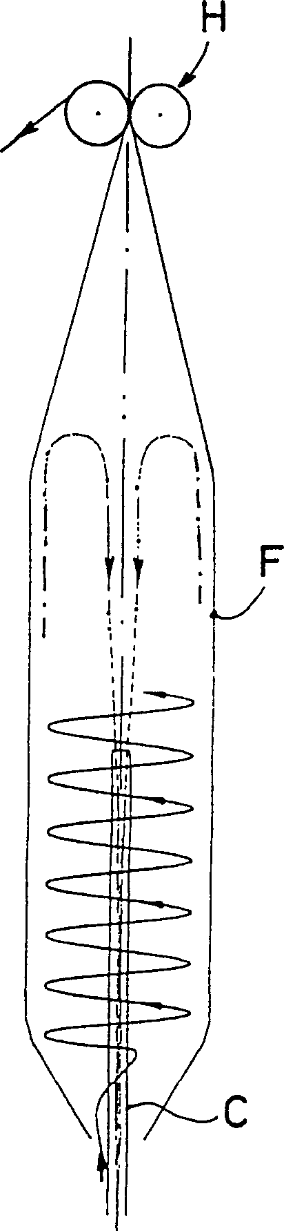
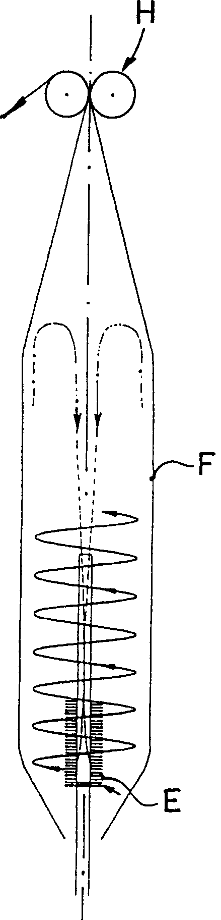
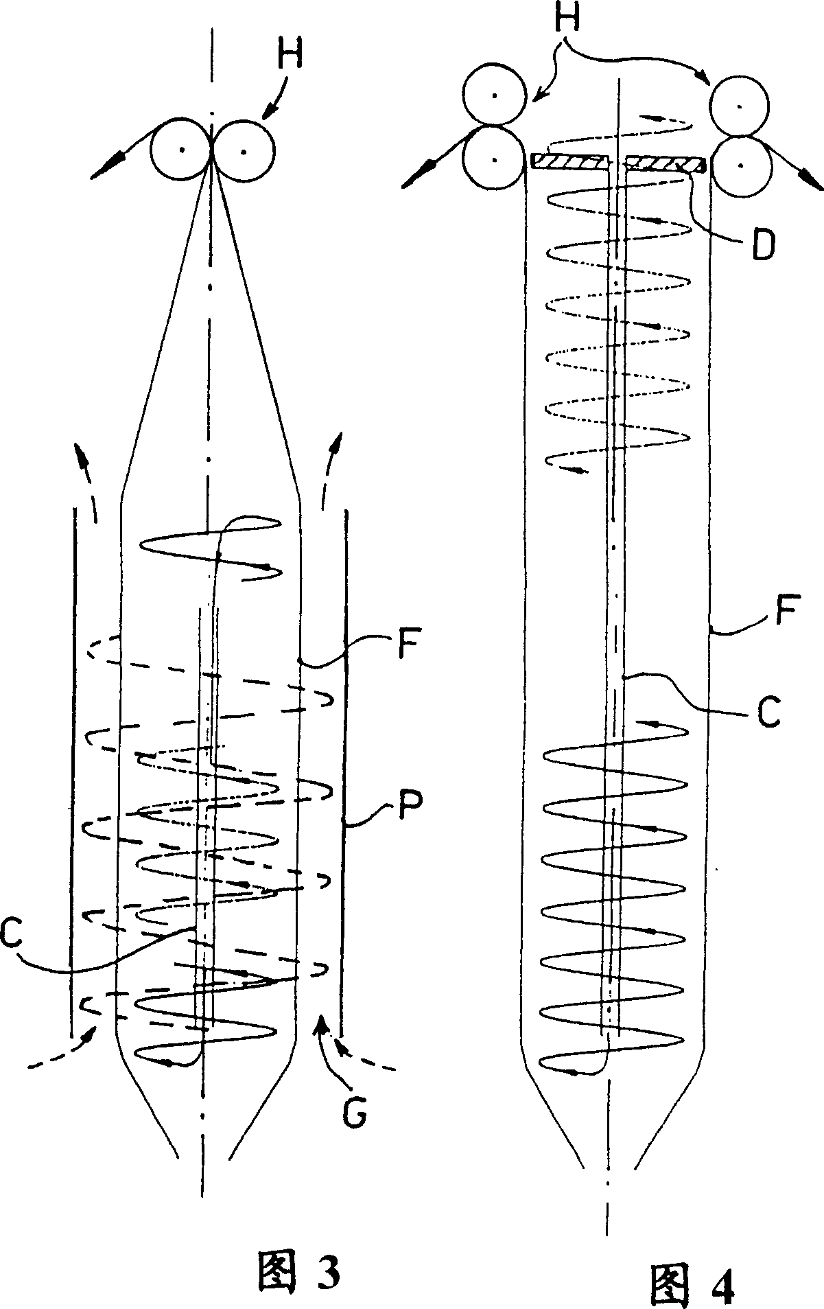
[0025] figure 1 Figure 4 shows a theoretical explanation and some potential implementations of the method and apparatus for film cooling according to the present invention.

[0026] refer to figure 1 , the first embodiment of the cooling technique according to the present invention shows a technique of internally cooling the film hose F just extruded from the nozzle hole (not shown) of the extruder. Pressurized air as coolant is fed in a transverse direction (as opposed to conventional delivery of coolant radially and in a direction parallel to the upward direction of hose advancement). In this way, the coolant flow is swirled (rotated) by the tangential inlet so that, according to the invention, due to the centrifugal force affecting the coolant flow along the inner surface of the film hose F, and the density difference between the different parts of the coolant flow and pressure difference, the coolant flow will follow a helical trajectory (shown as a solid line) in the cy...


PUM

PropertyMeasurementUnit
thicknessaaaaaaaaaa

Abstract

This invention relates to a method for cooling extruded plastic foil hose (F), which is cooled down by driving a pressurized coolant along the internal and / or external skirt of the foil hose (F). The coolant is fed in the area of a drawing aperture (4) tangentially to the foil hose (F), and the coolant thus generated is driven as a spiral stream (16, 17) from the tangential inlet (6) to the outlet by a centrifugal force affecting the coolant along the internal and / or external surface of the foil hose (F), and by the density and pressure differences between various parts of the coolant. Said apparatus (1) comprises an internal cooling unit (1B) equipped with a distribution drum (2) provided with nozzles (13) with tangential inlets (13A). Its external cooling unit (1A) has a tangential inlet (6), which is in connection with a ring channel (G) around the foil hose (F), delimited by a tubular element (5, P).

Description

technical field [0001] The present invention relates to a method and apparatus for cooling extruded plastic film hoses, ie blown tubular plastic films. Such plastic film hoses can be used, for example, for packaging various products. Background technique [0002] It is known that in a conventional method for the production of plastic film hoses (US-PS 5,607,639), the film hose is made of film material which is continuously extruded from the drawing orifice of the extruder nozzle, said film hose being produced in Properly stretched and oriented by blow molding, it is rapidly cooled. The cooling usually takes place with air flow by means of cooling rings cooling the outer surface of the film hose and / or units cooling the inner surface of the film hose. Each cooling unit draws heat from the film by heat transfer. [0003] US-PS 6,068,462 discloses a device for the continuous production of blown film hoses, which device is respectively provided with a first internal cooling u...

Claims


Application Information

Patent Timeline
Patent Type & Authority Applications(China)
IPC IPC(8): B29C47/88B29C48/10B29C48/32
CPCB29C47/883B29C2793/009B29C47/0026B29C47/8835B29C48/10B29C48/9125B29C48/913
Inventor A·佩茨T·伊莱什
Owner DR-派克Ⅱ有限公司
Why Eureka
Try Eureka