Centrifugal turbo machinery

a centrifugal turbo and machinery technology, applied in the direction of non-positive displacement fluid engines, radial flow pumps, pump components, etc., can solve the problems of leakage loss, disc friction loss, outer diameter of the impeller, etc., to reduce the speed difference the distance between the impeller and the casing can be gradually reduced, and the distance between the impeller and the casing can be rapidly reduced

Active Publication Date: 2019-02-21
MITSUBISHI HEAVY IND LTD
View PDF10 Cites 0 Cited by
  • Summary
  • Abstract
  • Description
  • Claims
  • Application Information

AI Technical Summary

Benefits of technology

[0016]According to this configuration, when the speed of the fluid between the impeller and the casing is increased, the distance between the impeller and the casing can be rapidly decreased, and when the speed of the fluid between the impeller and the casing is slowed down, the distance between the impeller and the casing can be gradually reduced.
[0017]According to t

Problems solved by technology

In an impeller of a centrifugal turbo machinery, a leakage loss occurs due to fluid leakage to a gap of an impeller rear side, and in addition, a friction loss (a disc friction loss) due to rotation of the disc in water occurs.
However, in a high-pressure pump (an injection pump, an electric submersible pump (ESP), a water supply pump, and the like) for which there is great need for petroleum gas, chemical plants and the like, an outer diameter of the impeller tends to increas

Method used


Image

  • Centrifugal turbo machinery
  • Centrifugal turbo machinery
  • Centrifugal turbo machinery

Examples


first embodiment

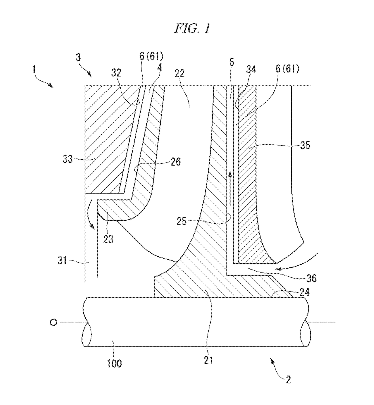
[0024]Hereinafter, a first embodiment in which the centrifugal turbo machinery of the present invention is configured as a multi-stage pump will be described with reference to the accompanying drawings.

[0025]As illustrated in FIG. 1, a centrifugal turbo machinery 1 includes a shaft 100 having an axis O, an impeller 2 fixed to the shaft 100 to be rotatable together with the shaft 100, and a casing 3 provided with a suction port 31 and accommodating the impeller 2. In the present specification, a direction toward the suction port 31 of the casing 3 with respect to the impeller 2 in an axial direction of the impeller 2 is defined as forward, and a direction toward an opposite side of the suction port 31 of the casing 3 with respect to the impeller 2 in the axial direction of the impeller 2 is defined as rearward.

[0026]The impeller 2 includes a disc 21 having a substantially disc shape when viewed in the axial direction, a plurality of blades 22 provided on the disc 21, and a cover 23 w...

second embodiment

[0036]A second embodiment of the present invention will be described with reference to FIG. 5. Hereinafter, only components different from those in the first embodiment will be described, and description of the same constituent elements as those of the first embodiment will not be provided. Constituent elements in the second embodiment the same as those in the first embodiment are denoted by the same reference numerals as in the first embodiment.

[0037]FIG. 5 is an axial cross-sectional view of the centrifugal turbo machinery 101 illustrating the arrangement of the waveform portions in the second embodiment.

[0038]The first embodiment is configured to have waveform portions 6 in the entire regions of the portions of the rear side 32 and the front side 34 facing the front side 26 and the rear side 25. However, in the second embodiment, the waveform portion 106 is formed only in a partial region on the radially outer side of the portions of a rear side 132 and a front side 134 facing th...

third embodiment

[0040]A third embodiment of the present invention will be described with reference to FIG. 6. Hereinafter, only components different from those in the first embodiment will be described, and description of constituent elements the same as in the first embodiment will be omitted. Reference numerals of the third embodiment which are the same as in the first embodiment denote constituent elements the same as those in the first embodiment.

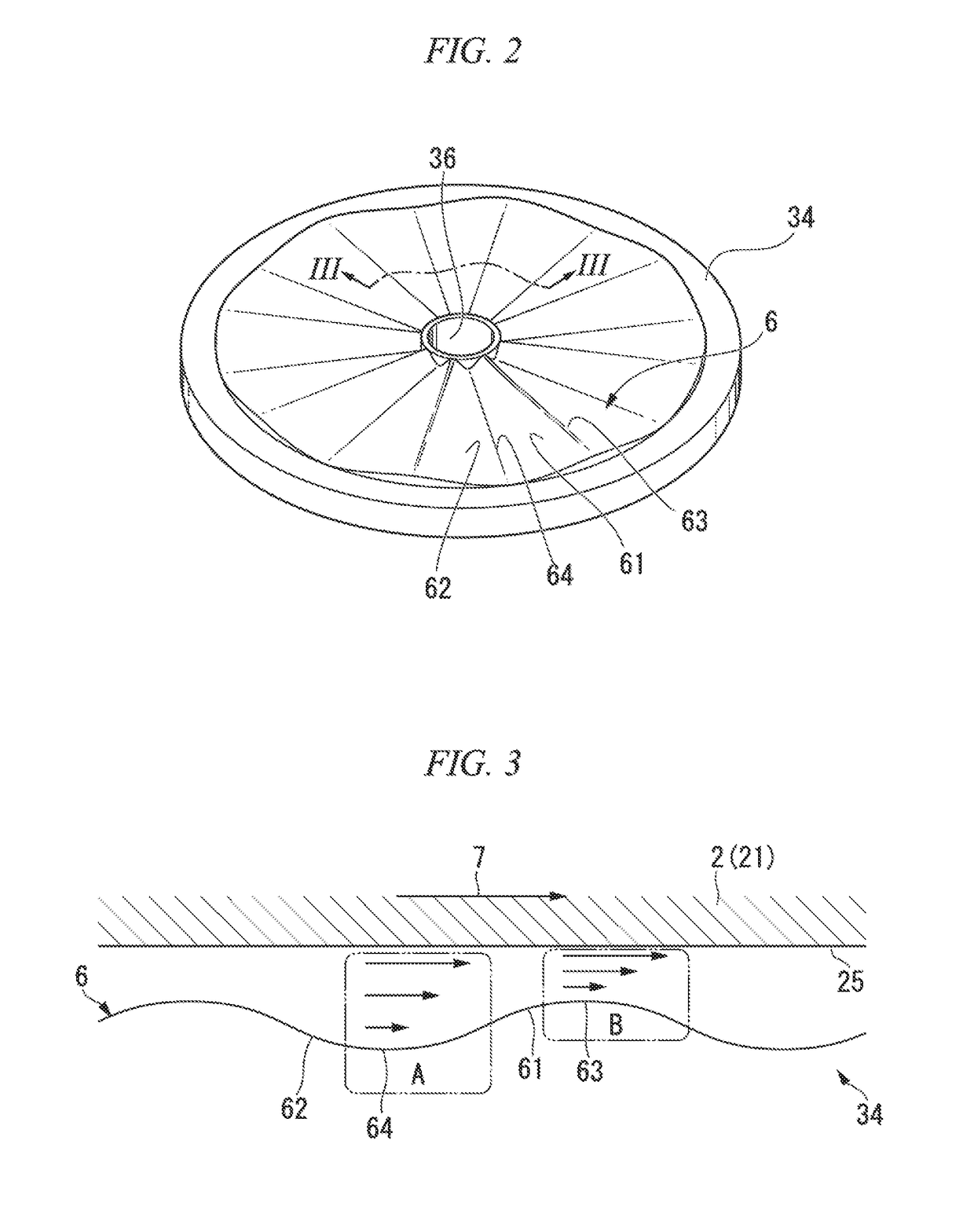
[0041]FIG. 6 is a diagram illustrating the configuration of the waveform portion 206 in the third embodiment and corresponding to FIG. 3 of the first embodiment.

[0042]In the first embodiment, each wave of the waveform portion 6 has a symmetrical configuration, but each wave of the third embodiment is configured asymmetrically. In the third embodiment, as illustrated in FIG. 6, assuming that the impeller 2 rotates in the rotational direction 7, in each wave, the convex portion 261 and the concave portion 262 of the waveform portion 206 formed on the fro...


PUM


Abstract

A centrifuge turbo machinery includes an impeller which rotates about an axis to pressure-feed fluid flowing along the axis to an outer side in a radial direction, and a casing which accommodates the impeller and has a facing surface facing the impeller in an axial direction. A convex portion relatively close to the impeller and extending in the radial direction and a concave portion relatively spaced apart from the impeller and extending in the radial direction are alternately and continuously formed on the facing surface in a circumferential direction.

Description

CROSS-REFERENCE TO RELATED APPLICATIONS[0001]Priority is claimed on Japanese Patent Application No. 2017-157052, filed Aug. 16, 2017, the content of which is incorporated herein by reference.BACKGROUND OF THE INVENTIONField of the Invention[0002]The present invention relates to a centrifugal turbo machinery.Description of Related Art[0003]In an impeller of a centrifugal turbo machinery, a leakage loss occurs due to fluid leakage to a gap of an impeller rear side, and in addition, a friction loss (a disc friction loss) due to rotation of the disc in water occurs. Since the disc friction loss is small in a low-pressure pump, the influence of the disc friction loss can be neglected. However, in a high-pressure pump (an injection pump, an electric submersible pump (ESP), a water supply pump, and the like) for which there is great need for petroleum gas, chemical plants and the like, an outer diameter of the impeller tends to increase, and a fraction accounted for by the disc friction lo...

Claims


Application Information

Patent Timeline
IPC IPC(8): F04D29/24F04D29/22F04D29/44F04D17/08
CPCF04D29/245F04D29/2272F04D29/44F04D17/08F05D2250/184F05D2240/14F04D1/063F04D29/2261F04D29/2266F04D29/284F04D29/681F04D29/688
Inventor SANO, TAKESHIASAHARA, TAIKI
Owner MITSUBISHI HEAVY IND LTD
Why Eureka
Try Eureka