Brake/drive force controlling apparatus for vehicle

a technology for controlling apparatus and brakes, which is applied in the direction of braking systems, instruments, braking systems, etc., can solve the problems of increasing difficult to obtain a target vehicle behavior, and difficulty in controlling the speed difference between the left and right driving wheels, so as to increase the size of the drive force distribution mechanism

Active Publication Date: 2017-10-17
TOYOTA JIDOSHA KK
View PDF18 Cites 0 Cited by
  • Summary
  • Abstract
  • Description
  • Claims
  • Application Information

AI Technical Summary

Benefits of technology

[0019]The brake / drive force controlling apparatus for the vehicle according to the present invention includes the drive source, the drive force distribution mechanism, and the brake force application mechanism. The control unit controls the drive force distribution mechanism and the brake force application mechanism according to the operating state of the vehicle. The drive force distribution control unit controls the operation of the drive force distribution mechanism according to the operating state of the brake force application mechanism. Accordingly, when the brake force application mechanism is operated and a speed difference between the left and right driving wheels suddenly increases, the operation of the drive force distribution mechanism is controlled beforehand regardless of the running state of the vehicle. Therefore, this controlling apparatus avoids sudden input of load on the drive force distribution mechanism, thus restraining the need to increase the size of the drive force distribution mechanism. This makes the apparatus simpler and more lightweight.

Problems solved by technology

This makes it difficult to control the speed difference between the left and right driving wheels, which are distributed by the drive force distributing mechanism.
If brake control, which uses the electronic control system brake device, and drive force distribution control for left and right driving wheels, which uses the drive force distribution mechanism, are simultaneously exerted, the speed difference between the left and right driving wheels increases, making it difficult to obtain a target vehicle behavior.

Method used


Image

  • Brake/drive force controlling apparatus for vehicle
  • Brake/drive force controlling apparatus for vehicle
  • Brake/drive force controlling apparatus for vehicle

Examples


embodiment

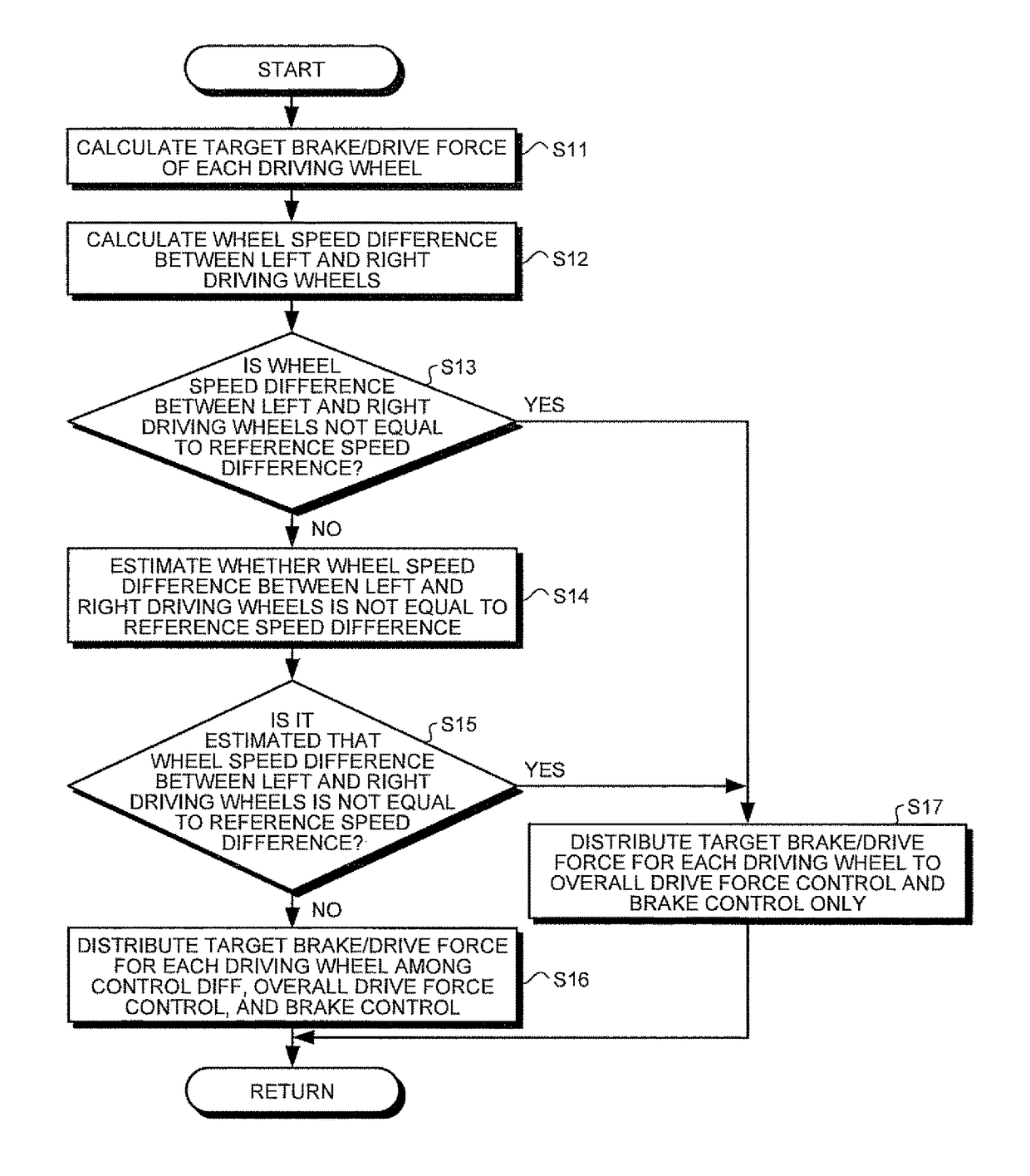
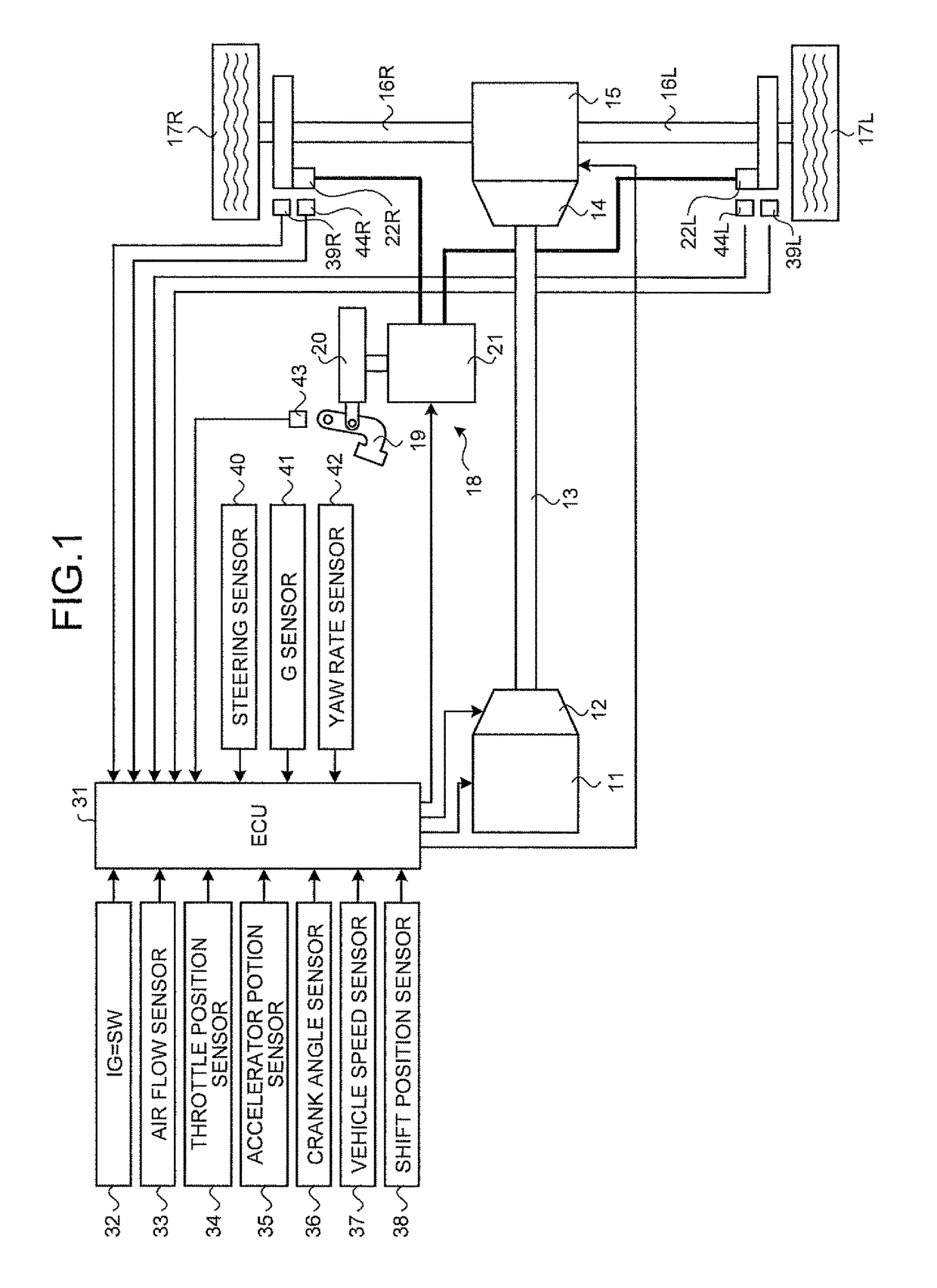
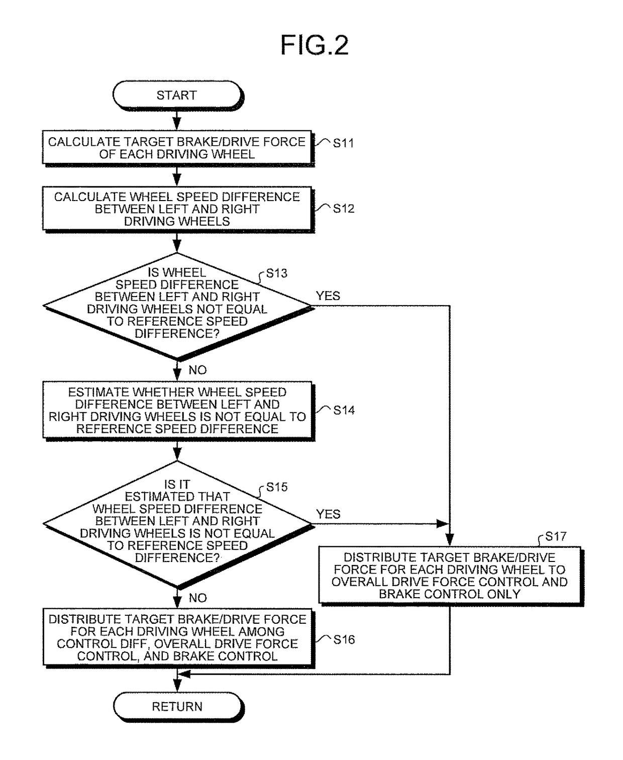
[0031]FIG. 1 is a schematic view illustrating a configuration of a brake / drive force controlling apparatus for a vehicle according to an embodiment of the invention. FIG. 2 is a flowchart illustrating vehicle behavior control exerted by the brake / drive force controlling apparatus for the vehicle according to the present embodiment.

[0032]In the brake / drive force controlling apparatus for the vehicle according to the embodiment, as shown in FIG. 1, an engine 11 serving as a drive source is mounted in the vehicle, and an automatic transmission 12 is mounted in the engine 11. The front end of a propeller shaft 13 is connected to an output shaft (not shown) of the automatic transmission 12. The other end of the propeller shaft 13 is connected to a viscous coupling 14 and a control differential (hereinafter referred to as “control diff”) 15, which serves as a drive force distribution mechanism in the present invention. One end of a drive shaft 16L and one end of a drive shaft 16R are conn...


PUM


Abstract

A brake / drive force controlling apparatus for a vehicle includes an engine for applying drive forces to driving wheels of the vehicles, a control diff for distributing the drive forces to the left and right driving wheels independently, and an electronic control system brake device for applying brake forces to the left and right driving wheels independently. An ECU is configured so as to be able to control the engine, the control diff, and the electronic control system brake device according to an operating state of the vehicle. When the electronic control system brake device is operated, this ECU stops the operation of the control diff, thereby avoiding a sudden input of load on the drive force distribution mechanism, regardless of the running state of the vehicle. This makes the apparatus simpler and more lightweight.

Description

TECHNICAL FIELD[0001]The present invention relates to a brake / drive force controlling apparatus for a vehicle, and more particularly the present invention relates to a brake / drive force controlling apparatus for a vehicle, which has a drive force distribution mechanism that distributes drive forces differentially to the left and right driving wheels.BACKGROUND ART[0002]Devices for distributing drive forces to the left and right driving wheels of a vehicle have been proposed. In one example of a left / right drive force distribution mechanism of a vehicle, the revolving speed of one of the left and right driving wheels is output after being increased or decreased by a predetermined change gear ratio; which output portion is then engaged with the other one of the left and right driving wheels, thereby transmitting drive torque from the faster revolving side to the slower revolving side. For example, if the revolving speed of one of the left and right driving wheels is increased and outp...

Claims


Application Information

Patent Timeline
Patent Type & Authority Patents(United States)
IPC IPC(8): B60W30/18B60W10/16B60K23/04B60T8/1755B60W10/184B60W10/06B60W10/04B60W10/12B60W10/18B60W10/188B60W30/02B60W30/184F16H48/20F16H48/22
CPCB60W30/18109B60K23/04B60T8/1755B60T2201/14B60T2260/08B60W10/06B60W10/16B60W10/184B60W2520/14B60W2540/12B60W2540/18
Inventor MIZOGUCHI, YOJITAGUCHI, KOJIKATO, HIROKAZU
Owner TOYOTA JIDOSHA KK
Why Eureka
Try Eureka