Reversible holes turning insert

A technology of inserts and inner holes, applied in turning equipment, tools for lathes, accessories of toolholders, etc., can solve the problems of limited inner hole finishing of workpieces, large cutting force, and uncontrollable or unpredictable chip flow. , to avoid interference and enhance sharpness

Inactive Publication Date: 2006-07-12
ZHUZHOU CEMENTED CARBIDE CUTTING TOOLS CO LTD
View PDF1 Cites 12 Cited by
  • Summary
  • Abstract
  • Description
  • Claims
  • Application Information

AI Technical Summary

Problems solved by technology

[0002] The processing of chips in internal hole turning has always been a major problem in machining, especially when processing small-diameter workpieces, chips are difficult to break and discharge, and are easy to wrap around workpieces, tools, and fixtures. The more accumulated, it is very easy to scratch the processed surface, affect the processing quality, and even hit the blade to cause the blade to break
The curvature of the chips formed by cutting is too large, the flow of chips cannot be controlled or predicted artificially, and the chips

Method used


Image

  • Reversible holes turning insert
  • Reversible holes turning insert
  • Reversible holes turning insert

Examples


Embodiment Construction

[0015] The present invention will be further elaborated below in conjunction with accompanying drawing:

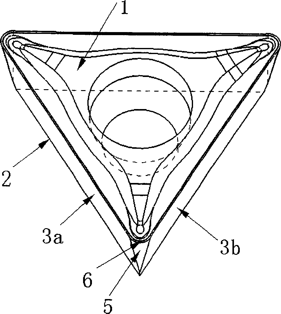
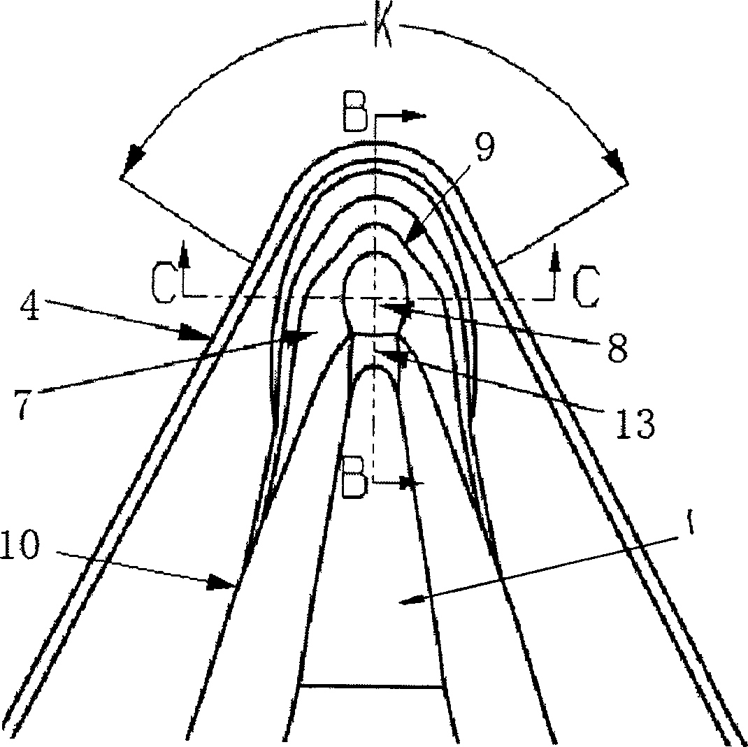
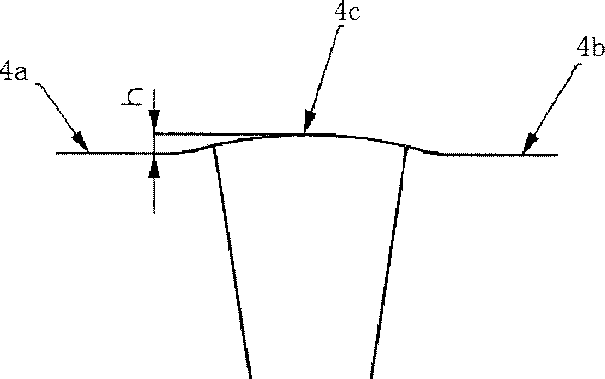
[0016] Such as Figure 1-Figure 6 As shown, the indexable inner hole turning insert of the present invention has a polygonal basic shape, such as a triangle, including opposite upper and lower surfaces 1, 2 and three groups of side walls 3 connecting the two, the side walls 3 and the upper surface 1 intersect to form the cutting edge 4 of the insert, where the upper surface 1 forms the rake face. The cutting edge 4 is distributed symmetrically with respect to the geometric bisector of the cutting edge angle 6, in the shape of a spatial helix, and the top edge 4c located on the geometric bisector of the cutting edge angle is at the highest position, and the maximum difference h between the symmetrical side edges 4a and 4b is 0.02 -0.2mm; Adjacent sidewalls 3a and 3b are connected by conical surface 5 to form a flank with a relief angle a of 5°-15°; upper surface 1, sidewal...


PUM


Abstract

The invention provides a variable-position turning cutter in polyton shape for accurately turning the internal hole, which comprises upper and lower surfaces and several side walls. Wherein, the side walls intersect the upper surfaces to form the cutting edge; and the upper surface forms the rack face of cutting edge. Said invention is characterized in that: two nearby side walls via taper surface are connected to form back face; upper surface, side wall and arc surface are intersected to form an angle of cutting edge; the cutting edges are symmetry distributed relative to the geometry bipartition of said angle of cutting edge to form spatial spiral line shape while the top edge is highest; a groove is arranged in the middle of top part of said cutting edge angle which also has a chip-breaker groove formed by spherical boss in said groove; the tail part of spherical boss via generatrix is connected to a cylinder surface with a ª’ relative to horizontal direction and the upper surface of cutting edge; the bottom of said groove is in ellipse shape and same height of the bottom of knife slit; and the side wall and the axes of blade have a included angle of ª‰. The inventive variable-position turning edge has sharp blade, controllable cutting direction and shape, which can remove chip successfully.

Description

technical field [0001] The invention relates to an indexable inner hole turning insert, in particular to an indexable cutting insert used in inner hole precision turning. Background technique [0002] The processing of chips in internal hole turning has always been a major problem in machining, especially when processing small-diameter workpieces, chips are difficult to break and discharge, and are easy to wrap around workpieces, tools, and fixtures. The more it accumulates, the easier it is to scratch the processed surface, affect the processing quality, and even hit the blade to cause the blade to chip. Therefore, in the traditional inner hole machining, the operator often has to stop the machine midway to clean up the chips, which seriously affects the machining efficiency and the machining quality of the workpiece. Especially for the precision machining of the inner hole of the workpiece, the problem of chip disposal is more prominent. The curvature of the chips formed...

Claims


Application Information

Patent Timeline
IPC IPC(8): B23B27/06B23B27/00
Inventor 刘敏王社权张京马志强何志平
Owner ZHUZHOU CEMENTED CARBIDE CUTTING TOOLS CO LTD
Why Eureka
Try Eureka