Flexible function blocks

A functional block, flexible technology, applied in the direction of program control, electrical program control, instruments, etc., can solve problems such as expensive and difficult to maintain

Inactive Publication Date: 2006-07-12
FIELDBUS FOUND
View PDF2 Cites 9 Cited by
  • Summary
  • Abstract
  • Description
  • Claims
  • Application Information

AI Technical Summary

Problems solved by technology

End users have to develop custom control software and specia

Method used


Image

  • Flexible function blocks
  • Flexible function blocks
  • Flexible function blocks

Examples


Embodiment Construction

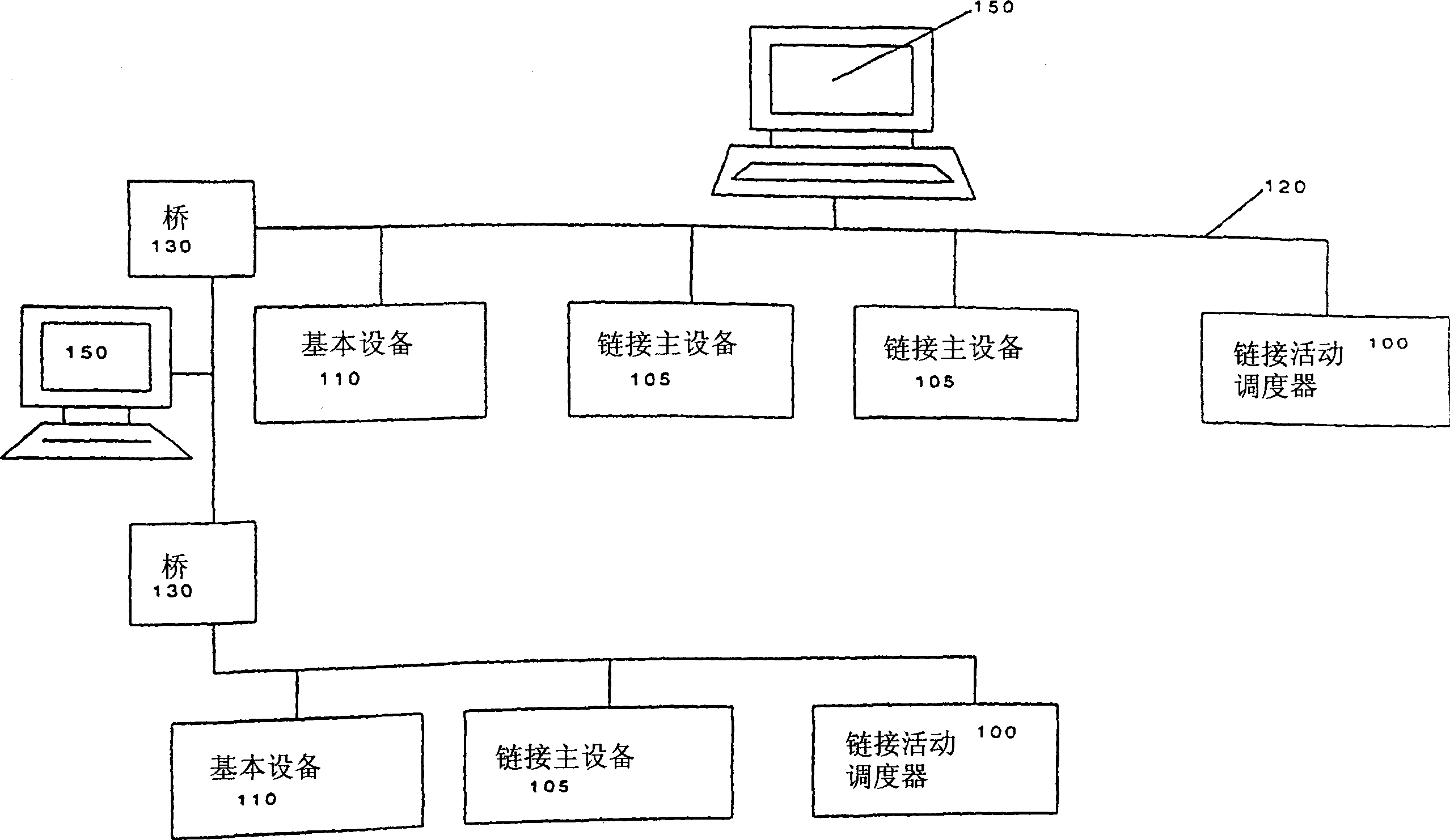
[0031] The following describes the improved interoperability, improved open control system, and improved distributed control that provide new, end-user configurable function blocks (flexible function blocks). The control system can support various types of field devices including converters and actuators, or high-speed field devices such as unit controls, motors, drivers, and remote input / output (I / O). Flexible function block enables the number and type of function block input / output (I / O), and the function block algorithm that can be configured by the end user. The following first provides an embodiment description of the control system ( Figure 1-12 ), and then describe the flexible function block ( Figure 13-15 ).

[0032] Such as figure 1 As shown, the field devices operating on the control system are generally classified as a connection effective scheduler 100, a connection master device 105, or a basic device 110. How to classify field devices depends on their control perf...


PUM


Abstract

A new and improved control system architecture using a combination of standard function blocks and new flexible function blocks eliminates the need for expensive and difficult to maintain custom control software and special I/O gateways for discrete/hybrid/batch and PLC applications. The end user builds application-specific flexible function blocks by configuring the number and type of inputs and outputs, and the block algorithm. Flexible function blocks and gateway flexible function block interconnect and interoperate with each other and with standard function blocks in a distributed control architecture.

Description

[0001] Cross reference of related applications [0002] This application claims the priority of U.S. Patent Application Serial No. 10 / 453,596. Technical field [0003] The invention relates to an automatic control system system. More precisely, the present invention relates to the extended automatic control system system described in US Patent No. 6,424,872 and US Patent Application No. 09 / 598,697 to include a new "flexible function fast", which is rapidly increased Apply for compatibility to include complex discrete / mixed / batch and PLC applications. Background technique [0004] Factory control systems have rapidly shifted from proprietary, centralized systems to open, decentralized fieldbus-based systems, such as FOUNDATON from the Fieldbus Consortium (Austin, Texas) TM Fieldbus. FOUNDATON TM The fieldbus designates a lower speed fieldbus (H1) for process control, and a high-speed Ethernet (HSE) fieldbus backbone link for high-performance control, subsystem integration, and mana...

Claims


Application Information

Patent Timeline
IPC IPC(8): G05B19/42G05B15/02G05B19/042G05B19/418H04L29/06H04L29/08
CPCH04L29/06068G05B15/02G05B2219/31118G05B2219/15068H04L29/08567H04L67/125H04L69/08H04L67/325G05B2219/13101G05B2219/25428G05B19/042G05B2219/13127H04L29/08963G05B19/056G05B2219/25085G05B2219/23256H04L67/62
Inventor D·A·格兰泽S·B·米奇克W·M·霍金斯M·冯·乐·叙尔S·H·塔特西
Owner FIELDBUS FOUND
Why Eureka
Try Eureka