Laser cutting of thick metal parts with a dual-focus lens

A technology for metal workpieces and lenses, applied in metal processing equipment, lenses, laser welding equipment, etc.

Inactive Publication Date: 2006-07-19
LAIR LIQUIDE SA POUR LETUDE & LEXPLOITATION DES PROCEDES GEORGES CLAUDE
View PDF1 Cites 4 Cited by
  • Summary
  • Abstract
  • Description
  • Claims
  • Application Information

AI Technical Summary

Problems solved by technology

[0014] Despite the teachings of this document, it has been found in practice that f

Method used


Image

  • Laser cutting of thick metal parts with a dual-focus lens
  • Laser cutting of thick metal parts with a dual-focus lens
  • Laser cutting of thick metal parts with a dual-focus lens

Examples


Embodiment Construction

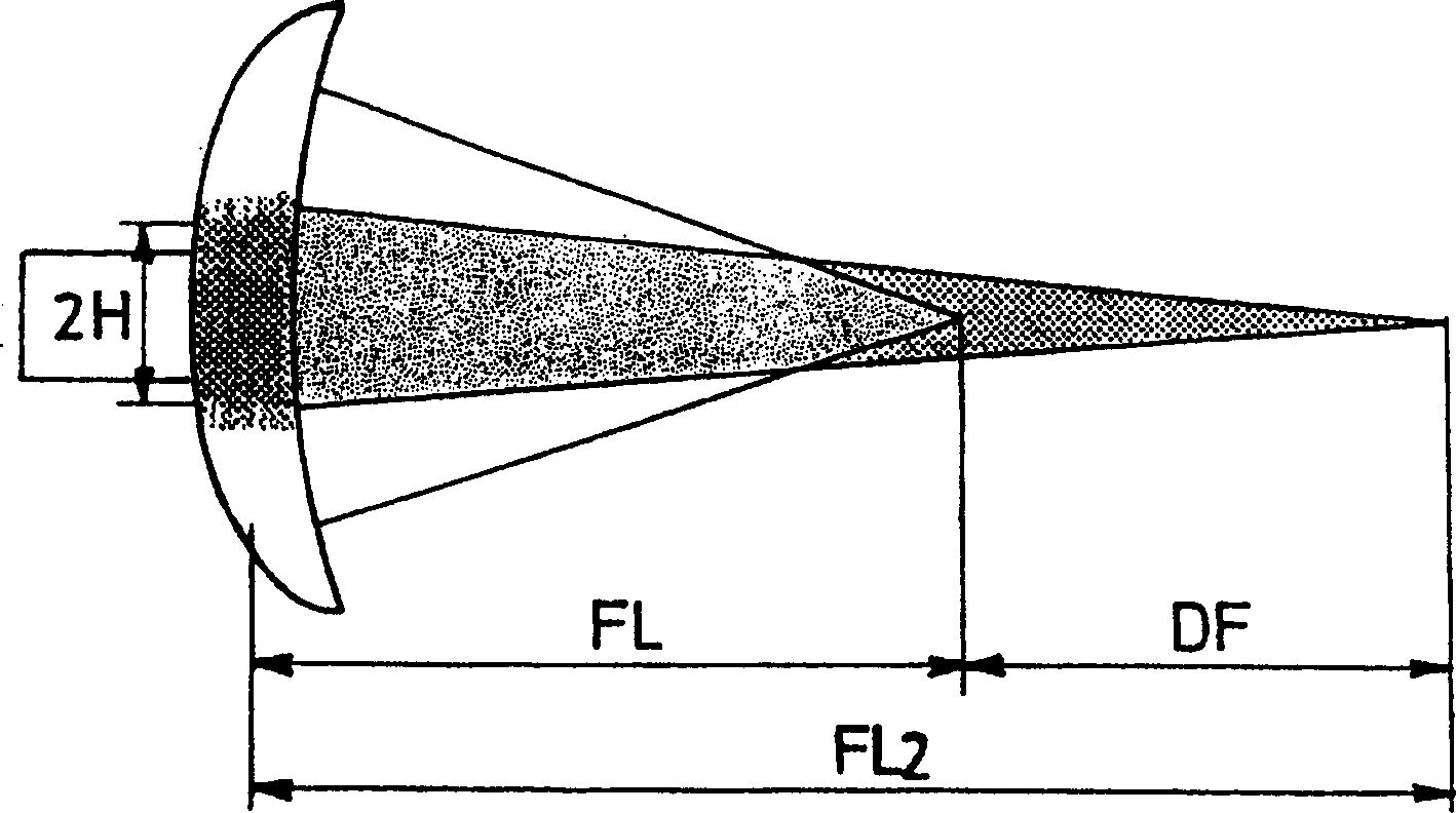
[0033] When it came to the solution of the above-mentioned problems, the inventors of the present invention noticed that the laser cutting method using a bifocal lens depends on the parameters of the lens used, namely its focal length FL, (diameter) 2H and (distance) DF, such as figure 1 shown in .

[0034] The 2H value of a lens corresponds to that diameter of the central region of the lens whose radius of curvature differs from that of the peripheral portion of the lens. The part of the incident beam lying outside the diameter 2H is focused on a first focal point PF1 at the main focal length FL. The part of the incident laser beam lying within the diameter 2H is focused on a second focal point PF2 at the main focal length FL2. The size of the diameter 2H determines the amount of energy concentrated at the second focal point PF2.

[0035] The distance DF corresponds accordingly to the difference between the focal lengths FL and FL2, as figure 1 shown.

[0036] example

...


PUM

PropertyMeasurementUnit
Thicknessaaaaaaaaaa
Diameteraaaaaaaaaa
Poweraaaaaaaaaa

Abstract

Methods for laser beam cutting metal workpieces with a thickness between 4 mm and 25 mm. A double focusing lens is provided to make it possible to focus a laser beam on a first focusing and a second focusing point. These points are separate from each other and both lie on the laser's optical axis. The lens has a focal length between 170 mm and 300 mm.

Description

technical field [0001] The present invention relates to a laser beam cutting method using a lens with a double focusing function and a selected focal length. Background technique [0002] The laser cutting method conventionally employs a laser beam emitted by, for example, a carbon dioxide (λ=10.6 micron) type or YAG type laser processing machine (laser), which is focused by an optical element - usually a lens or mirror with a given focal length onto the workpiece to be cut. The cutting groove is usually injected with pressurized assist gas to remove molten metal. The cutting groove is formed by the relative movement between the cutting head, which consists of a focusing element that emits a laser beam and releases an assist gas, and the workpiece to be cut. [0003] Transmission focusing optics, or lenses, are the most common elements used in laser cutting because they create a pressurized, sealed cavity in the cutting head into which an assist gas can be injected and the...

Claims


Application Information

Patent Timeline
IPC IPC(8): B23K26/04B23K26/14G02B3/10B23K26/00
CPCB23K26/38B23K26/067B23K26/0617B23K26/0604
Inventor K·舒弗H·马扎维C·贝尔特兹
Owner LAIR LIQUIDE SA POUR LETUDE & LEXPLOITATION DES PROCEDES GEORGES CLAUDE
Why Eureka
Try Eureka