Throttle system device with annunciator

A system device and signal device technology, applied in the direction of mechanical control device, control/regulation system, power device control mechanism layout, etc., to achieve the effect of reducing accidents

Inactive Publication Date: 2006-07-19
ZHEJIANG XIANAN AUTOMOBILE BREAKING SYST
View PDF6 Cites 45 Cited by
  • Summary
  • Abstract
  • Description
  • Claims
  • Application Information

AI Technical Summary

Problems solved by technology

[0005] The purpose of the present invention is to solve the problem of accidents caused by stepping on the accelerator pedal by mistake in an emergency state that should be braked immediately, and provide a technical solution for correctly and accurately starting the remedial braking (braking) of stepping on the accelerator by mistake, so that the accelerator pedal can be operated under normal force. A dual-purpose motor vehicle accelerator system device that maintains the original acceleration (throttle) function at the same time as the speed (impulse), and has the braking (braking) function only under the action of unconventional large force and speed (impulse).

Method used


Image

  • Throttle system device with annunciator
  • Throttle system device with annunciator
  • Throttle system device with annunciator

Examples


Embodiment 1

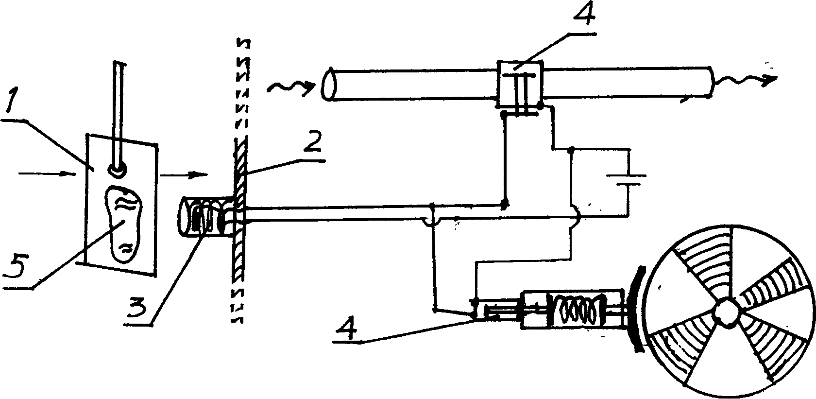
[0035] Embodiment 1: The annunciator 3 is fixed on the face of the people's feet 5 of the accelerator pedal 1 with screws. then press as image 3 The annunciator 3 forms a closed loop with the power supply and two electric valves 4 connected in parallel. An electric valve 4 is installed on the automobile oil supply pipe to control whether the oil pipe supplies oil; another electric valve 4 is installed on the automobile brake device to control whether to brake.

Embodiment 2

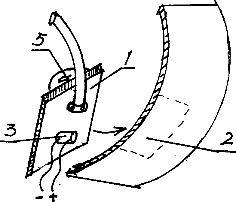
[0036] Embodiment 2: as figure 2 The annunciator 3 is fixed on the back side of the accelerator pedal 1 with screws, that is, between the accelerator pedal 1 and the vehicle body device 2 . Such as image 3 The annunciator 3 forms a closed loop with the power supply and two electric valves 4 connected in parallel. An electric valve 4 is installed on the automobile oil supply pipe to control whether the oil pipe supplies oil; another electric valve 4 is installed on the automobile brake device to control whether to brake.

Embodiment 3

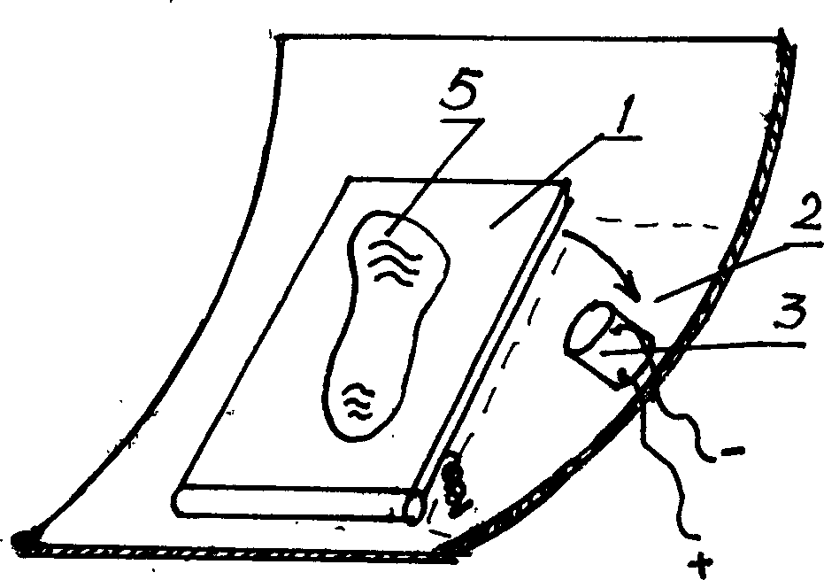
[0037] Embodiment 3: as figure 1 The signal device 3 is fixed on the vehicle body device 2 with screws, and is located between the accelerator pedal 1 and the vehicle body device 2 . The annunciator 3 forms a closed loop with the power supply and two electric valves 4 connected in parallel. An electric valve 4 is installed on the power supply wire of the battery car to control whether the oil pipe supplies power; the other electric valve 4 is installed on the automobile braking device to control whether to brake.


PUM


Abstract

The invention relates to an accelerator with a signal device, belonging to the technique of braking device and accelerator. The invention can overcome the defects of present accelerator pedal which can only accelerate the vehicle. It can make operation after judging if the motion of accelerator is right. It is characterized in that: a signal device 3 is arranged on any one of accelerator pedal 1, transmission device 4, and vehicle body 2. It has the advantages that: it can transform the wrong operation into right operation (braking) to reduce the accidence caused by wrong operation, with significant practicality.

Description

technical field [0001] The invention belongs to the technical field of braking devices and accelerating devices of motor vehicles, in particular to an accelerator pedal system of the accelerating device. Background technique [0002] The brake pedal of the existing motor vehicle braking device and the gas pedal of the acceleration device are all arranged separately, and have a certain distance apart, to prevent the driver from misoperation. However, when braking is required in an emergency, the driver accidentally steps on the accelerator pedal, which causes the vehicle to accelerate and cause an accident. The two opposite functions of braking and accelerating are reasonable in normal driving using two independent separated pedals. But the independent function of this separate pedal can not solve the problem of accident caused by stepping on the accelerator pedal by mistake in the emergency state that should brake immediately. [0003] In order t...

Claims


Application Information

Patent Timeline
Patent Type & Authority Applications(China)
IPC IPC(8): F02D11/02B60K26/00G05G1/14G05G1/30
Inventor 颜昌松
Owner ZHEJIANG XIANAN AUTOMOBILE BREAKING SYST
Why Eureka
Try Eureka