Air pressure engine

An engine and air pressure technology, which is applied in the direction of machines/engines, rotary piston engines, rotary or swinging piston engines, etc., can solve the problems of air pollution, high maintenance costs, and low work efficiency, and achieve no pollution to the environment and low maintenance costs , high work efficiency

Inactive Publication Date: 2006-07-19
于永海
View PDF0 Cites 1 Cited by
  • Summary
  • Abstract
  • Description
  • Claims
  • Application Information

AI Technical Summary

Problems solved by technology

[0002] The existing engine consumes energy, pollutes the environment, consumes oil every time it does work, pollutes the atmosphere, has low work efficiency, complex structure, large wear and tear of parts, and high maintenance costs

Method used


Image

  • Air pressure engine

Examples


Embodiment Construction

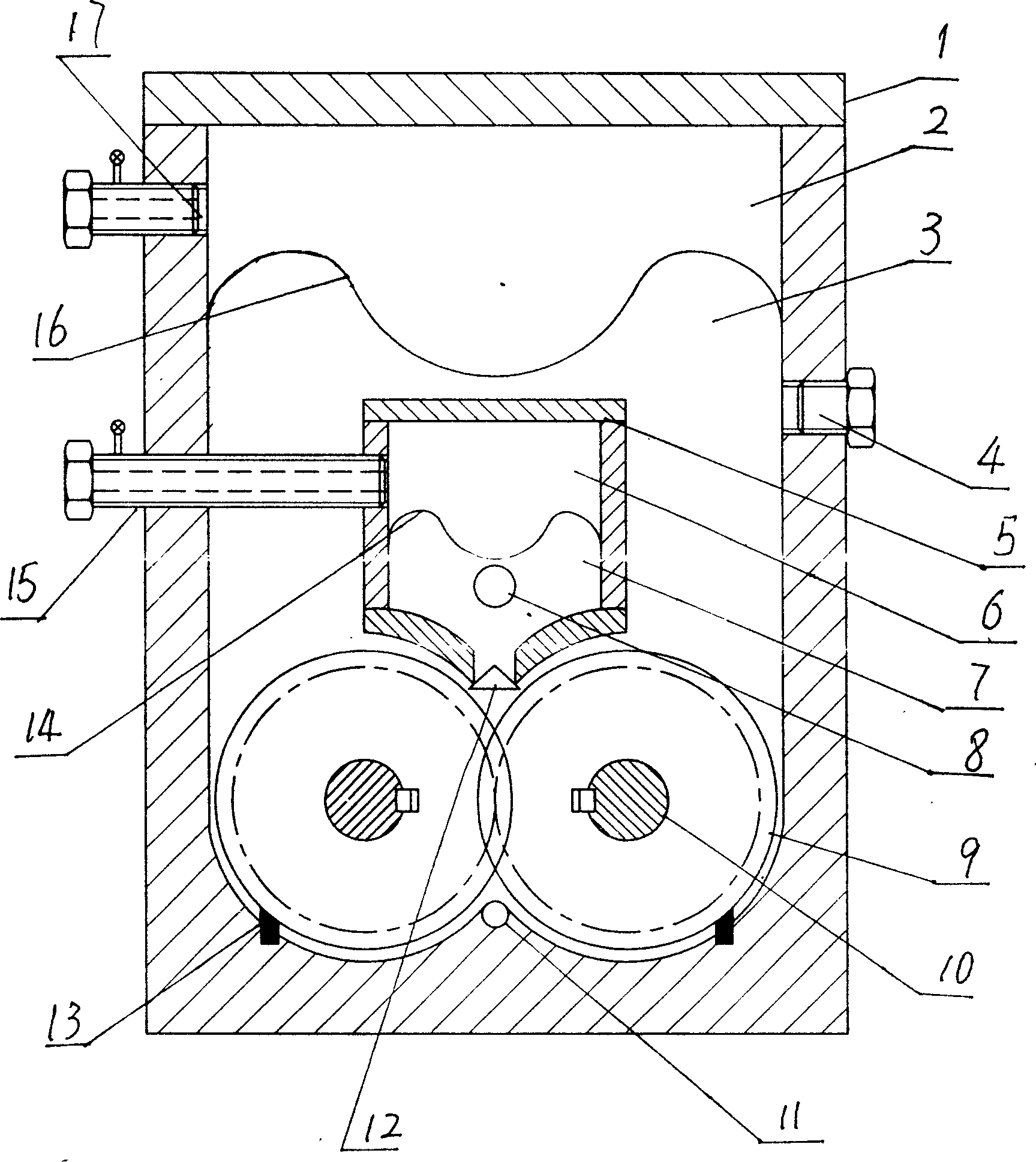
[0007] The present invention will be further described below in conjunction with the accompanying drawings and embodiments.

[0008] The present invention is made up of casing 1, case cover, gear 8 etc. The specific structure is as figure 1 , the upper part of the box body 1 is cast with a high-pressure chamber 2, and the high-pressure oil chamber 3 is located under the high-pressure chamber 2. In order to isolate the contact between the gas and the oil, a layer is set between the high-pressure oil chamber 3 and the high-pressure chamber 2 Air pressure diaphragm 13. An inner box body 4 is installed in the box body 1, and the inner box body 4 is located at the bottom of the high-pressure oil chamber 3. The inner box 4 is divided into two chambers, the upper chamber is the low-pressure chamber 5, and the lower chamber is the low-pressure oil chamber 6. In order to isolate the contact between the gas and the oil, an air pressure chamber is installed between the low-pressure cha...


PUM


Abstract

The invention relates to an air pressure motor, which comprises a box, a box cover and gears. Wherein, the box has a high-pressure air room whose lower part is high-pressure oil chamber; one side of high-pressure oil room has a oil feeding inlet; the power gear is at the lower end of high-pressure oil chamber; the inner box is inside the box whose upper part is low-pressure air room; the lower part of low-pressure air room is low-pressure oil chamber whose lower part has a decompression oil outlet and a return oil outlet through to the high-pressure oil chamber; the oil inlet has a float one-way valve; and a oil brush is arranged between the lower part of box and the gear. The invention has simple structure, less return oil, high working efficiency, and lower maintenance cost without environment pollution.

Description

technical field [0001] The invention relates to an engine, in particular to a pneumatic engine. Background technique [0002] The existing engine consumes energy, pollutes the environment, consumes oil every time it does work, pollutes the atmosphere, has low work efficiency, complex structure, large wear and tear of parts, and high maintenance costs. In today's severe energy shortage, it is urgent to improve the engine to save energy. Contents of the invention [0003] The purpose of the present invention is to provide a pneumatic engine with simple work procedure, only need to inflate the engine, does not burn oil, high working efficiency, and less wear and tear of parts. [0004] The technical scheme for realizing the above-mentioned invention purpose is: comprising a box body, a box body cover, a high-pressure air chamber is arranged in the box body, the lower part of the high-pressure air chamber is a high-pressure oil chamber, one side of the high-pressure oil chamb...

Claims


Application Information

Patent Timeline
IPC IPC(8): F03C2/08
Inventor 于永海
Owner 于永海
Why Eureka
Try Eureka