Stator for reciprocating motor and fabrication method thereof

A reciprocating and stator technology, which is used in the manufacture of motor generators, stator/rotor bodies, and electric components, etc., can solve the problems of high manufacturing costs and complex manufacturing processes.

Inactive Publication Date: 2006-07-19
INTELLECTUAL DISCOVERY CO LTD
View PDF0 Cites 4 Cited by
  • Summary
  • Abstract
  • Description
  • Claims
  • Application Information

AI Technical Summary

Problems solved by technology

Therefore, there are problems such as complicated manufacturing process and high manufacturing cost

Method used


Image

  • Stator for reciprocating motor and fabrication method thereof
  • Stator for reciprocating motor and fabrication method thereof
  • Stator for reciprocating motor and fabrication method thereof

Examples


Embodiment Construction

[0036] Reference will now be made in detail to the preferred embodiments of the present invention, examples of which are illustrated in the accompanying drawings.

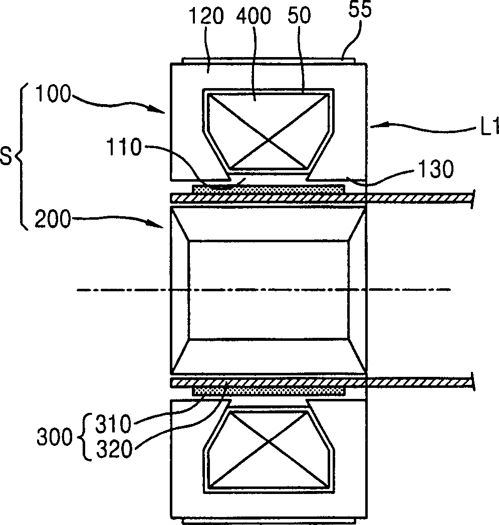
[0037] Fig. 4 is a cross-sectional view showing a reciprocating motor having a stator according to the present invention.

[0038] As shown therein, a reciprocating motor includes a stator S having an outer core 100 and an inner core 200 disposed in the outer core 100, and a mover 300 movably inserted between the outer core 100 and the inner core 200 of the stator S. in the gap between. The mover 300 includes one or more permanent magnets 310 and a magnet holder 320 for holding the permanent magnets 310 .

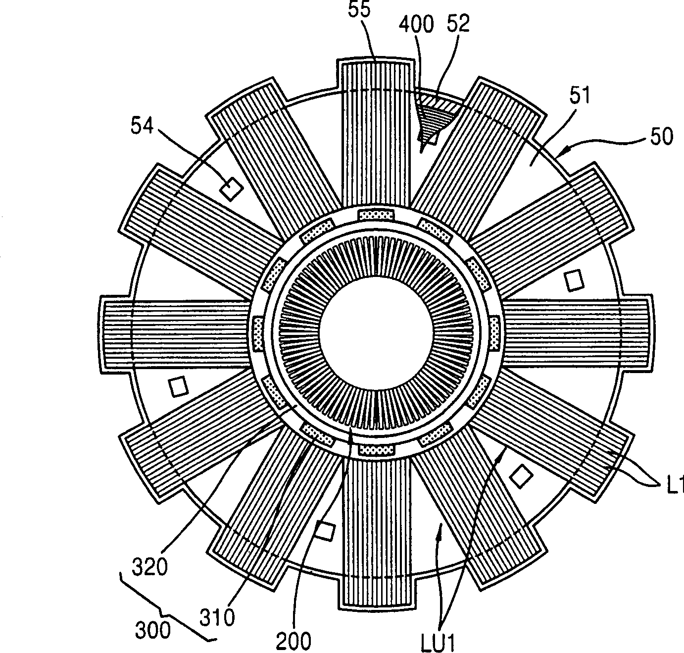
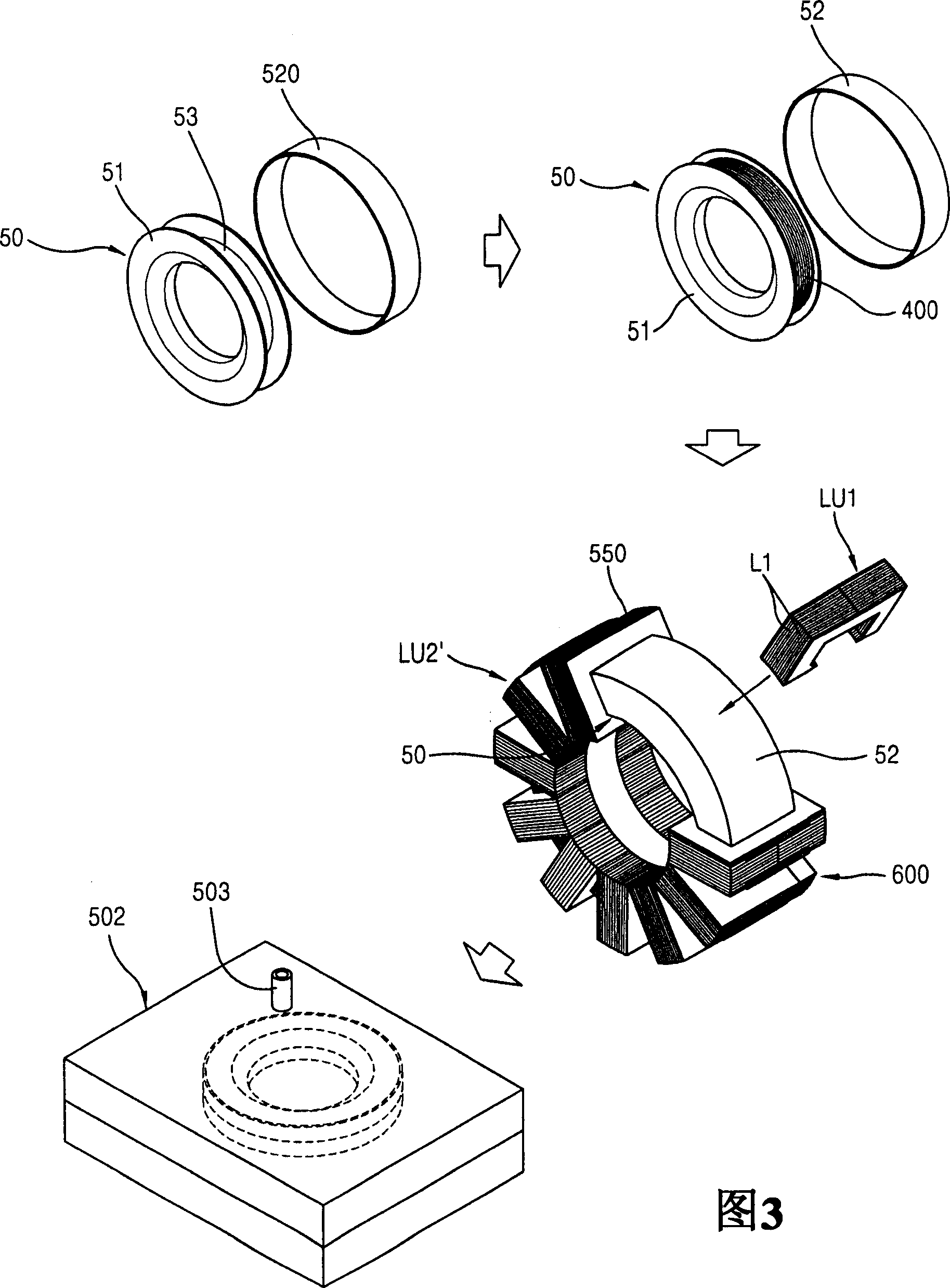
[0039] The outer core 100 includes a toroidal coil winding 400 in which the coil is wound multiple times and is fastened and insulated by an adhesive material 710 distributed between the coil windings; a circular strip shape for forming the insulating layer; an annular bobbin 500 comprising two halves 510 and ...


PUM


Abstract

A stator for a reciprocating motor includes a coil winding in which a coil is wound plural times, and fixed and insulated with a bonding material distributed between gaps of the wound coil, an insulation band formed in a circular band shape along an outer circumferential surface of the coil winding, an annular bobbin coupled to both side surfaces of the coil winding and covering the coil winding together with the insulation band, a plurality of core blocks coupled on the bobbin in a circumferential direction, and an inner core inserted with a certain interval from the circular inner circumferential surface formed by the bobbin and the plurality of core blocks.

Description

technical field [0001] The present invention relates to a reciprocating motor, and in particular, to a stator of a reciprocating motor and a manufacturing method thereof capable of simplifying a manufacturing process and preventing dimensional errors when injection molding is used. Background technique [0002] Electric motors convert electrical energy into kinetic energy. Motors are divided into rotary motors that convert electrical energy into rotational force and reciprocating motors that convert electrical energy into linear power. [0003] figure 1 is a cross-sectional view showing an example of a conventional reciprocating motor. As shown therein, the reciprocating motor includes a stator S having an outer core 100 and an inner core 200 located inside the outer core 100; move in. The mover 300 includes a permanent magnet 310 and a magnet holder 320 for holding the permanent magnet 310 . In the outer core 100 , the coil winding 400 is combined with the bobbin 50 in...

Claims


Application Information

Patent Timeline
Patent Type & Authority Applications(China)
IPC IPC(8): H02K1/12H02K15/02H02K33/00
CPCH02K15/12H02K15/02H02K33/16H02K1/145A43C3/00
Inventor 金成钟郑相燮
Owner INTELLECTUAL DISCOVERY CO LTD
Why Eureka
Try Eureka