Light tunnel of dlp projection system

A digital light processing and projection system technology, applied in the field of light tunnels, can solve the problems of reducing surface light, reducing image quality, poor reflection angle of reflectors, etc., to achieve uniform surface light and improve image quality

Inactive Publication Date: 2006-07-19
LG ELECTRONICS INC
View PDF0 Cites 3 Cited by
  • Summary
  • Abstract
  • Description
  • Claims
  • Application Information

AI Technical Summary

Problems solved by technology

[0007] To describe in detail, in the case where a connection portion between a fixed light tunnel and a reflection plate is heated and melted, a plurality of reflection plates are connected to each other to cause a problem of collapsing the light tunnel, and the connection force between the heat-treated reflection plates The reflection angle of the reflector becomes poor when dropped outside of the original position and reduces the ability to be used to form surface lights in light tunnels
If the light capacity of the surface is deteriorated, due to the failure of the light tunnel profile, the uniformity of the light surface is reduced and the image quality is reduced

Method used


Image

  • Light tunnel of dlp projection system
  • Light tunnel of dlp projection system
  • Light tunnel of dlp projection system

Examples


no. 1 example

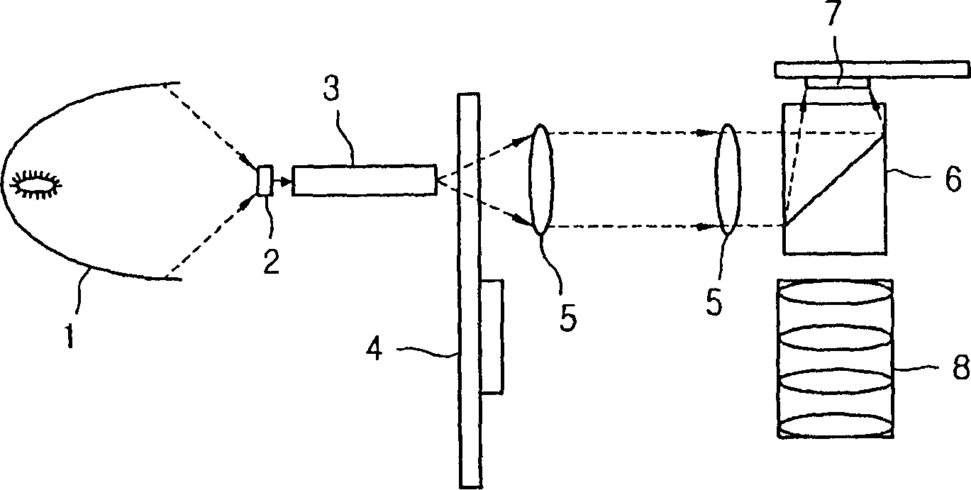
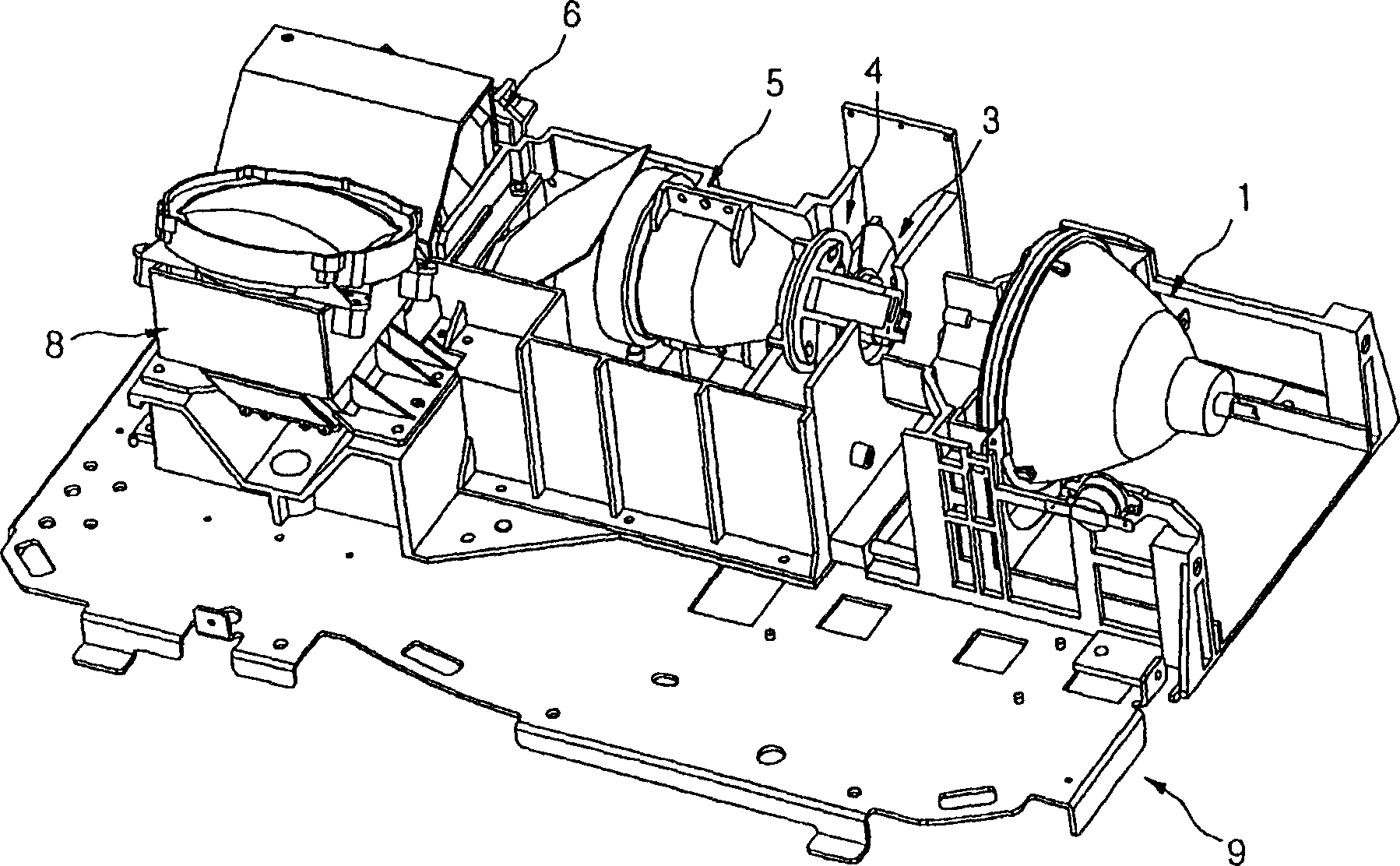
[0033] figure 1 is a structural diagram showing the structure of a DLP projection system according to the present invention, figure 2 is a perspective view of a light engine in a DLP projection system according to the present invention.

[0034] refer to figure 1 and 2 , the DLP projection system includes: a lamp 1 that generates light; a light tunnel portion 3 through which the light generated from the lamp 1 propagates; a color wheel 4 wherein the white light propagated through the light tunnel portion 3 is divided into RGB; a condenser lens 5, Concentrate the light passing through the color wheel 4; the prism 6, where the light passing through the condenser lens 5 is reflected; the DMD7, which focuses the light reflected on the prism 6 to the screen; and the projection lens 8, which amplifies the light reflected from the DMD7. In particular, the light tunnel 3 is formed so that the propagation of light generated from the lamp 1 has a uniform surface light source. Howev...

no. 2 example

[0057] Figure 5 is a lower perspective view in a detached state of the fixed slats in the light tunnel section according to the present invention, Image 6 is a lower perspective view in a state where the fixing strip is mounted on the light tunnel portion.

[0058] refer to Figure 5 and 6 , the light tunnel part of the DLP projection system according to the present embodiment includes: a light tunnel 130; a bracket 134, wherein the light tunnel is installed so as to be fixed to the light engine base; Light irradiated through other parts than the light tunnel 130 is shielded.

[0059] The light tunnel forms a reflective plate 132 in which a reflector having a reflective surface 132a is formed to reflect / refract the light projected in the light tunnel into a uniform surface light source. The size of the reflecting plate 132 forms a small shape with a length of 30mm, a width of 6.2mm, a height of 5.2mm and a thickness of 0.5mm.

[0060] The light tunnel 130 includes refle...

no. 3 example

[0069] The third embodiment of the present invention describes that the fixed slats included on the front of the light tunnel in the second embodiment can be included on the rear of the light tunnel, and the heat of the light tunnel in this embodiment is rapidly absorbed by the fixed slats. Radiates forward and backward from the light tunnel.

[0070] Figure 8 is a lower perspective view of a light tunnel according to a third embodiment, and Figure 9 Yes Figure 8 The cross-sectional view of the line I-I' in.

[0071] refer to Figure 8 and 9 , the light tunnel 130 reaches the arrival surface 136 of the bracket 134 , and the fixing strips 100 are respectively extended to the front and rear surfaces where light is irradiated and emitted to fix the light tunnel 130 to the bracket 134 . The fixing strip 100 is closely adhered to the front and rear surfaces of the bracket 134 in which the light tunnel 130 is installed so as to gently perform heat radiation and firmly suppor...


PUM


Abstract

In order to provide a light transmitting space to reinforce the strength of a light tunnel in a DLP projection system, and increase heat-resistance to warping or bowing, a light tunnel of a DLP projection system includes a plurality of reflection panels provided in an anteroposterior direction; a holder where the reflection panel is placed; a first supporting member supporting an end of the reflection panel; and a second supporting member supporting a body of the reflection panel.

Description

technical field [0001] The present invention relates to a light tunnel of a digital light processing DLP projection system with improved operational reliability, and more particularly to a light tunnel of a DLP projection system with increased radiation capability of the light tunnel, wherein a plurality of reflective plates are connected and their structure is firmly supported State, irradiate a lot of light. Background technique [0002] A method for realizing a high-quality image is implemented using a device that reflects light in a DLP projection system. The present invention relates to a device for displaying a high-brightness and high-resolution image by selectively reflecting light in the device, wherein the component Hundreds of reflective devices are integrated into a single chip. [0003] The DLP method projection system is a digital device that uses a control circuit to determine the shielding / opening of light reflected on the surface of a large number of tiny d...

Claims


Application Information

Patent Timeline
Patent Type & Authority Applications(China)
IPC IPC(8): H04N5/74H04N9/31
CPCE04B9/0435E04B9/068E04B9/28
Inventor 吴南锡吴相旻吕振东
Owner LG ELECTRONICS INC
Why Eureka
Try Eureka