Valve control device reducing noise

A valve control and controller technology, applied in engine control, charging system, internal combustion piston engine, etc., can solve problems such as increasing the trouble of car occupants

Active Publication Date: 2006-08-02
DENSO CORP +1
View PDF2 Cites 6 Cited by
  • Summary
  • Abstract
  • Description
  • Claims
  • Application Information

AI Technical Summary

Problems solved by technology

Therefore, the noise accompanying the removal of deposits reache

Method used


Image

  • Valve control device reducing noise
  • Valve control device reducing noise
  • Valve control device reducing noise

Examples


Embodiment Construction

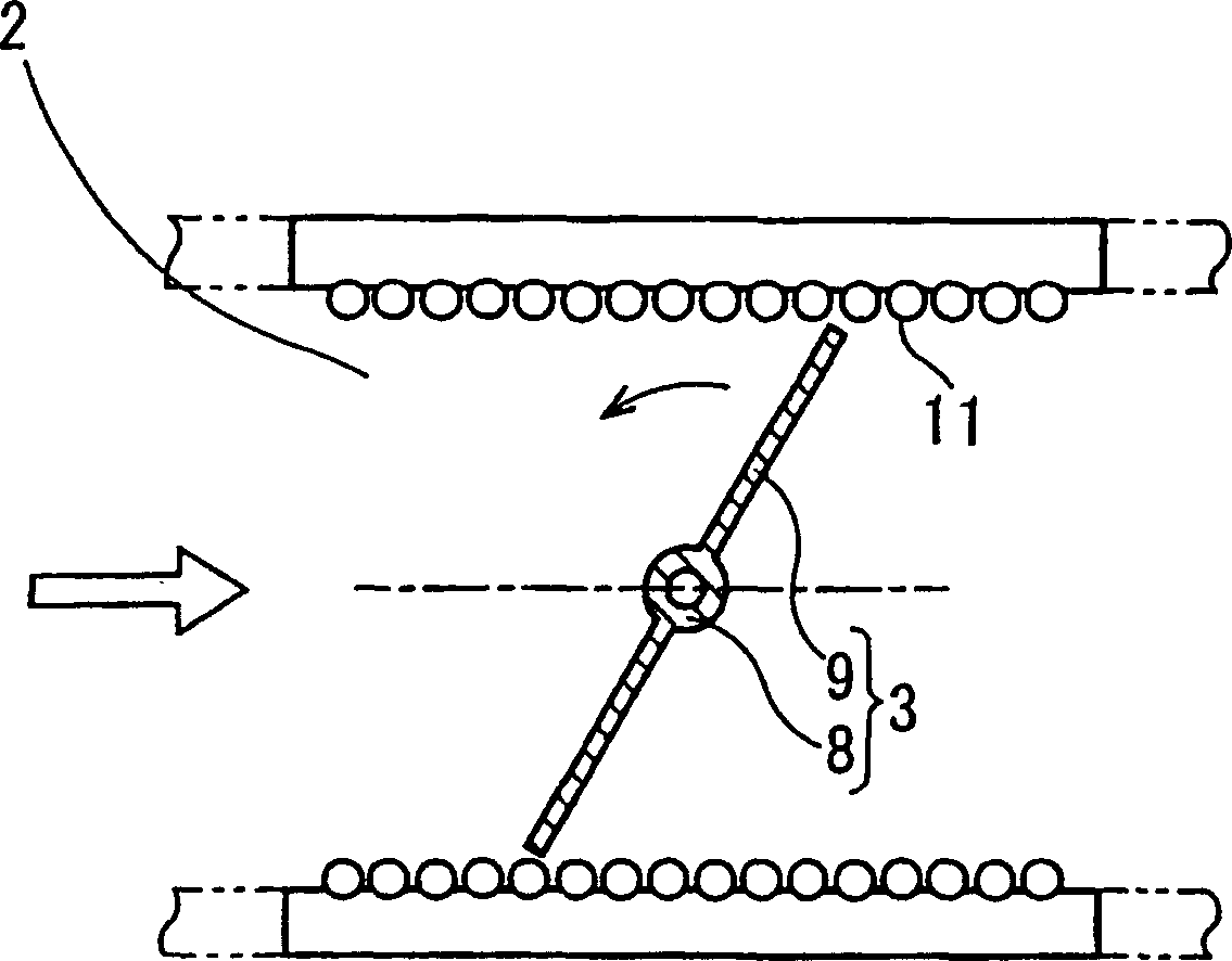
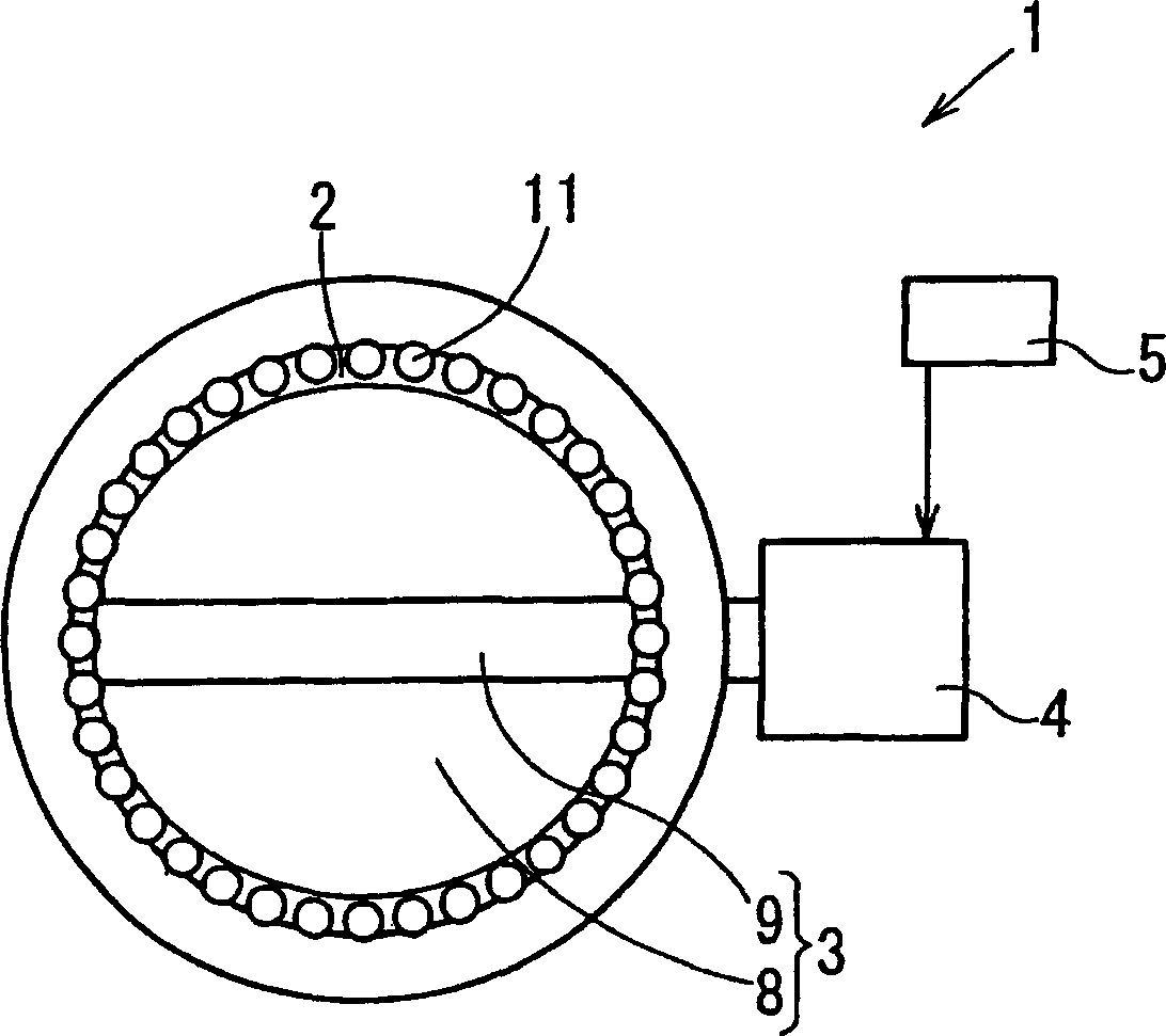
[0020] refer to Figure 1A and Figure 1B , shows a valve control device 1 according to a first embodiment of the invention, which drives and controls a valve 3, such as a throttle valve, an exhaust gas recirculation valve (EGR valve), or an exhaust gas restrictor valve. Through the valves, fluid enters and or discharges from the engine passages.

[0021] This valve arrangement 1 is inserted into a flow channel 2 which carries out the air supply and exhaust gas discharge of the engine. The valve control device 1 has a valve 3 , a motor 4 , and an electronic control unit (ECU) 5 . Valve 3 regulates the flow rate of intake or exhaust. The motor 4 is an actuator that drives the valve 3 . The ECU 5 functions as a controller to drive and control the valve 3 by controlling the operation of the motor 4 .

[0022] For example, the valve 3 is a disc valve having a shaft portion 8 connected to a rotation shaft (not shown) of the motor 4 and a substantially circular plate portion 9 ...


PUM


Abstract

A valve control device corrects a change rate of an opening degree of a valve in accordance with engine rotation speed when deposit elimination operation is performed. The valve control device corrects an inclination between a positive maximum opening degree and a negative maximum opening degree of the valve in accordance with the engine rotation speed when the deposit elimination operation is performed. Thus, when the engine rotation speed is low and a noise accompanying the deposit elimination operation becomes more audible, the change rate of the opening degree of the valve is reduced. As a result, the noise accompanying the deposit elimination operation is reduced and annoyance for vehicle occupants is reduced.

Description

technical field [0001] The invention relates to a control device for a valve, such as a throttle valve or an exhaust gas recirculation valve (EGR valve), which is installed in a flow channel for engine air supply or exhaust gas discharge. Background technique [0002] The valve control unit performs the removal of deposits in the valve, such as a throttle valve or an exhaust gas recirculation valve, to prevent the valve from malfunctioning due to deposits such as oil mist or oil smoke adhering to the flow channel wall (EGR valve), which is installed in the flow path for engine air supply or exhaust gas discharge. [0003] Removal of deposits in the valve may be performed by driving the valve through a fully closed valve position when valve operation has little effect on engine operating conditions, such as when the engine is stopped. The valve is driven not only in the valve opening direction from the fully closed position but also in the closing direction opposite to the v...

Claims


Application Information

Patent Timeline
IPC IPC(8): F02D9/02F02D9/08F02M26/50F02M26/52
CPCY02T10/121
Inventor 竹本英嗣胜野佑人藤田达也难波邦夫中山庆则
Owner DENSO CORP
Why Eureka
Try Eureka