
An induction conveying device and a conveyor

A technology of conveying device and conveying mechanism, which is applied to conveyors, conveyor objects, conveyor control devices, etc., can solve problems such as affecting the working efficiency of the crusher, uneven feeding, etc., achieving simple structure, slowing down work efficiency, and increasing The effect of drive speed

Active Publication Date: 2021-08-17
济南鲁平建材有限公司
View PDF8 Cites 0 Cited by
  • Summary
  • Abstract
  • Description
  • Claims
  • Application Information

AI Technical Summary

Problems solved by technology

[0005] In order to alleviate the problem of affecting the working efficiency of the crusher caused by uneven feeding per unit time, the application provides an induction conveying device and a conveyor

Method used


Image

  • An induction conveying device and a conveyor
  • An induction conveying device and a conveyor
  • An induction conveying device and a conveyor

Examples


Embodiment 1

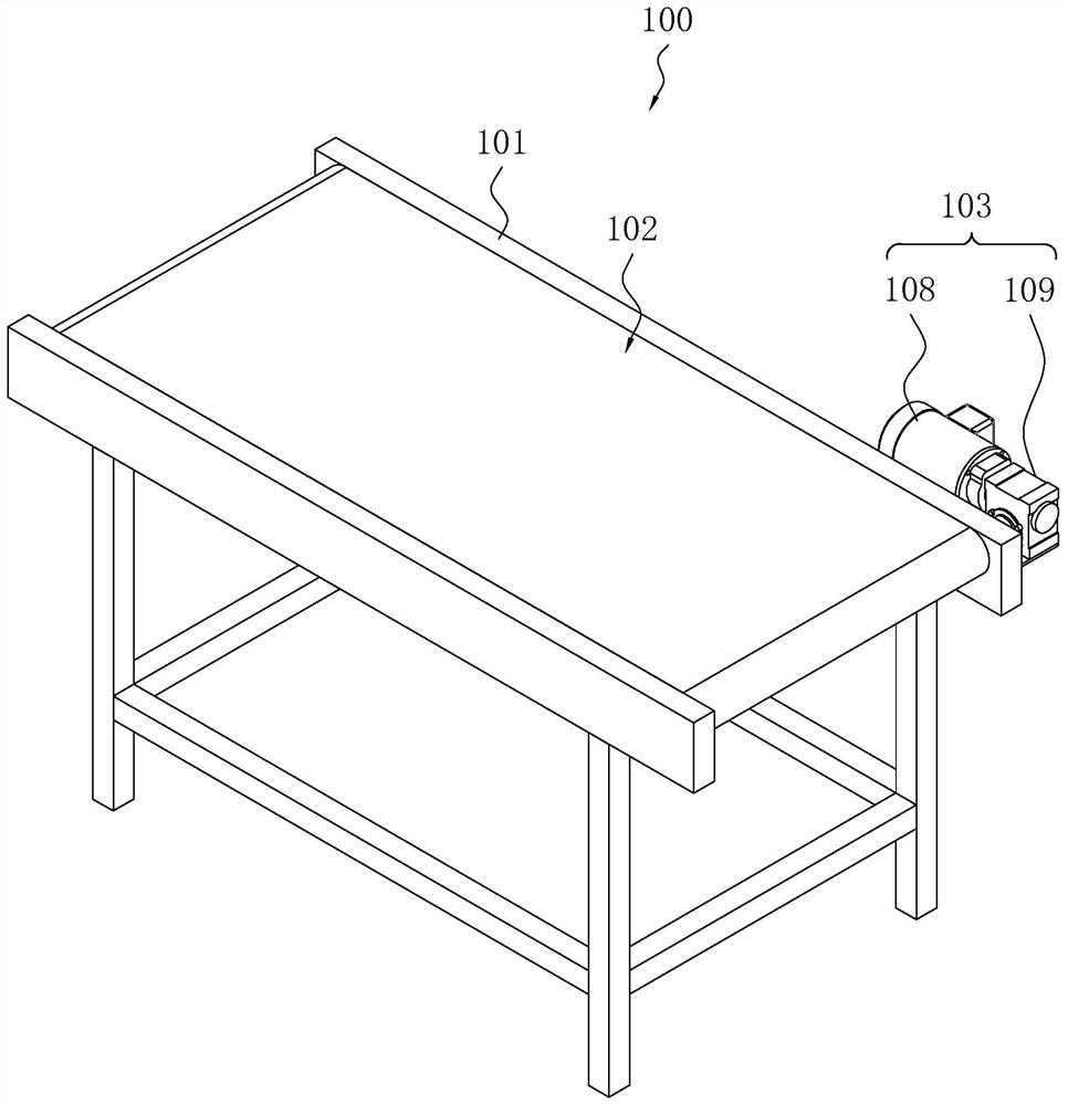
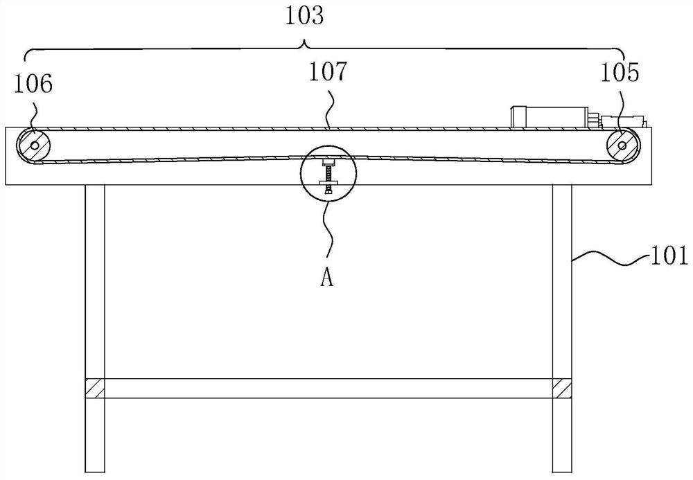
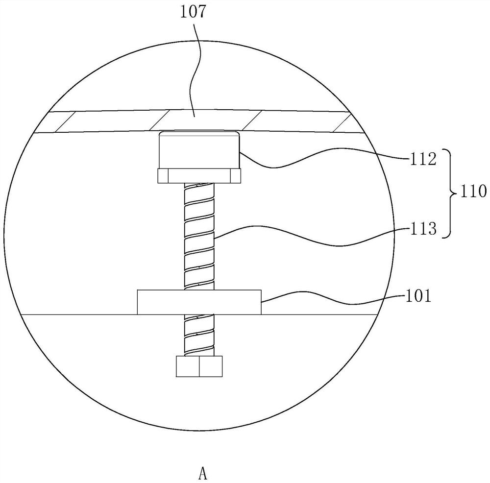
[0044] refer to figure 1 , an induction conveying device 100 includes a frame 101, which is connected with a conveying mechanism 102, a driving mechanism 103 and a detecting mechanism. The conveying mechanism 102 is used for conveying materials horizontally or obliquely. The driving mechanism 103 is connected with the conveying mechanism 102 and provides power for the conveying mechanism 102 . The detection mechanism is used to detect the weight of the material conveyed on the conveying mechanism 102, and control the driving speed of the driving mechanism 103 so that the driving speed of the driving mechanism 103 slows down as the weight of the conveyed material on the conveying mechanism 102 increases.

[0045] refer to figure 1 , the detection mechanism detects the weight of the material conveyed on the conveying mechanism 102, judges the amount of material on the conveying mechanism 102 by the weight of the material, and then controls the driving speed of the driving mech...

Embodiment 2

[0052] refer to Figure 4 , an inductive conveying device 100 , which differs from Embodiment 1 in that a load detection component 110 is present.

[0053] refer to Figure 4 , the load detection component 110 includes a DC drive motor 114 and a current sensor for detecting the current intensity of the DC drive motor 114 . The DC drive motor 114 is fixedly connected to the frame 101 and its main shaft is coaxially fixedly connected to the end of the driving roller 105 away from the servo motor 109 .

[0054] The PLC controller is electrically connected with a timer. After every X seconds, the PLC controller 111 controls the servo motor 109 to stop working and controls the DC drive motor 114 to work for Y seconds, and utilizes the current sensor to detect the current of the DC drive motor 114 when it is working, thereby Judging the weight of the material on the conveying mechanism 102, then controlling the servo motor 109 to continue working for X seconds, as before, without ...


PUM


Abstract

The application relates to an induction conveying device and a conveyor, which includes a frame; a conveying mechanism, connected to the frame and used for horizontal or inclined conveying of materials; a driving mechanism, connected with the conveying mechanism and providing power for the conveying mechanism; a detection mechanism, It is electrically connected with the driving mechanism, and is used for detecting the weight of the material conveyed on the conveying mechanism, and controlling the driving speed of the driving mechanism, and the driving speed of the driving mechanism decreases as the weight of the conveyed material on the conveying mechanism increases. The application has the effect of alleviating the problems affecting the working efficiency of the crusher.

Description

technical field [0001] The present application relates to the field of conveyors, in particular to an induction conveying device and a conveyor. Background technique [0002] The hammer crusher is a kind of equipment for crushing stones in the form of impact. It is a crusher for crushing stones with a maximum particle size of 600-1800 mm to 25 or less. The hammer crusher is suitable for crushing medium-hard stones in cement, chemical, electric power, metallurgy and other industrial sectors, such as limestone, slag, coke, coal and other stones for medium and fine crushing operations. [0003] In order to realize automatic feeding, conveyor belts are often used to feed crushers. However, because different methods are used to transport materials, the materials per unit area are inconsistent, resulting in inconsistent materials delivered to the crusher per unit time. If there is too much, it may cause the feed port of the crusher to be blocked, and if it is too small, the crush...

Claims


Application Information

Patent Timeline
Patent Type & Authority Patents(China)
IPC IPC(8): B65G43/08B65G23/22B65G23/04B65G23/30B02C13/286
CPCB02C13/286B02C2013/28636B65G23/04B65G23/22B65G23/30B65G43/08B65G2203/0258B65G2203/042
Inventor 姚庆成刘万军姚吉旺李传坤
Owner 济南鲁平建材有限公司
Learn More