Optical communication system using optical frequency code, optical transmission device and optical reception device thereof, and reflection type optical communication device

An optical communication system and optical coding technology, applied in the field of optical communication systems, can solve problems such as deterioration of communication quality and poor extinction ratio of downlink optical signals, and achieve the effect of rough control accuracy and easy realization

Inactive Publication Date: 2006-08-02
NIPPON TELEGRAPH & TELEPHONE CORP
View PDF1 Cites 14 Cited by
  • Summary
  • Abstract
  • Description
  • Claims
  • Application Information

AI Technical Summary

Problems solved by technology

Therefore, the following problem arises: the wavelength of the transmitted optical signal and the selected wavelength 31 of the encoder 11 are notified from the receiving end to the transmitting end, and the transmitting end must correct the outgoing light 20 of the light source 10 and the selected wavelength 31 of the encoder 11 based on the notification.
Therefore, the extinction ratio of the downlink optical signal is poor, and the communication quality deteriorates

Method used


Image

  • Optical communication system using optical frequency code, optical transmission device and optical reception device thereof, and reflection type optical communication device
  • Optical communication system using optical frequency code, optical transmission device and optical reception device thereof, and reflection type optical communication device
  • Optical communication system using optical frequency code, optical transmission device and optical reception device thereof, and reflection type optical communication device

Examples


no. 1 approach

[0112] First Embodiment (Optical Code Multiplexing)

[0113] The first embodiment of the present invention can perform optical code multiplexing, but it can also not be optical multiplexing, that is, it is applied to the optical communication of a data sequence. In order to make the title of this item easy to distinguish from the implementation mode, add brackets and write as (optical code multiplexing).

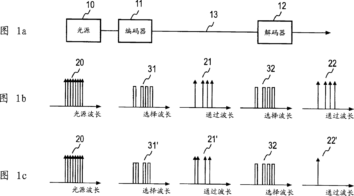
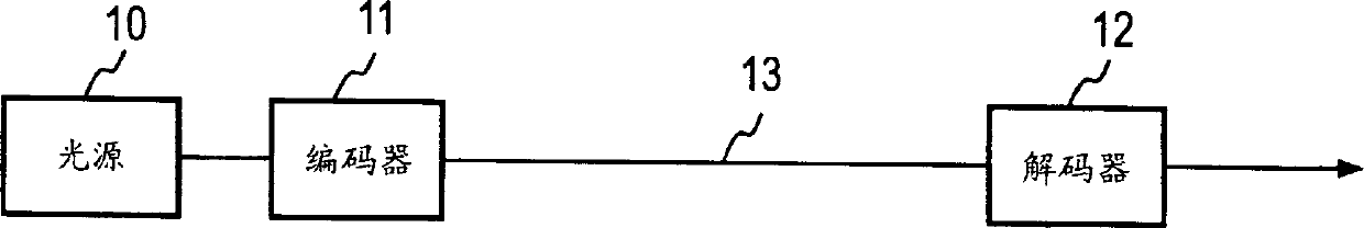
[0114] First, examples of transmitting and receiving side devices to which the present invention can be applied will be described. FIG. 2(a) shows an example of an optical transmission end device to which the first embodiment is applied. n=1, 2, ..., N (N is an integer greater than or equal to 2), the light source 10 n and encoder 11 n group of 14 via fiber n Connect to multiplexer 15. Each encoder 11 n Input data sequence D in n , data sequence D n by Encoder 11 n Encoded as an optically encoded signal through optical fiber 14 n It is input to the multiplexer 15 a...

Embodiment 1-1

[0118] FIG. 4 shows a communication system of a system to which Example 1-1 of the first embodiment can be applied. This embodiment 1-1 is the same as the existing optical communication system, has a light source 10, an encoder 11, a decoder 12, an optical transmission path (optical fiber) 13, and furthermore, includes a dispersion compensator 17 in this embodiment 1-1, Since the frequency-dependent propagation delay time differs due to the frequency dispersion of the optical transmission path, average compensation is performed so that the delay time between transmission and reception of each frequency component constituting the optical coded signal is the same. The optical frequency region to be compensated by the dispersion compensator 17 is at least wider than the optical frequency region used as the optical code signal.

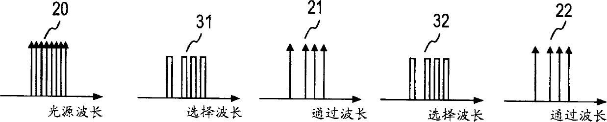
[0119] The light source 10 outputs at least an optical signal of an optical bandwidth FSR corresponding to a code length FCL (common multiple of FSRi des...

Embodiment 1-2

[0139] Example 1-2 of the first embodiment is a concrete example of Example 1-1, and is an example using a trigonometric function as the coding function C(f). In the present embodiment 1-2, use the value of a as small as possible (positive integer), and under the situation that r ' codes are generated with the same value of a, a takes from 1 to the maximum number of codes (maximum coverage encoder Number) N divided by the integer value of the value N / r' of r', when r is set to 0, 1, ..., r'-1 of the remainder of r', as the nth light The coded signal Cn(f) is represented by the following formula.

[0140] Cn(f)=(1+cos(2·π·a·f / FCL+r·π / 2)) / 2 (7)

[0141] The optically encoded signal function value Cn(f) is a value from 0 to 1, and the encoder 11 n The integral value in the interval of any code length FCL in the encoding object is FCL / 2, and the encoder 11 n In the optical frequency region to be coded, the light transmission characteristic repeats the function value Cn(f) withi...


PUM


Abstract

The correction of the light frequency of a light source may not be needed, a transmission belt is not increased, but a plurality codes are used. The light frequency width of the light source is set to be FSR and the code length of all codes are set to be FSR and is enabled to be provided with the orthogonality. Each light intensity frequency characteristic of an nth optical coded signal is set to be Cn(f)=[1+cos(2pion sf/FSR+r pion/2)/2(s is an integer of 1-the maximum code/2, r=0or1)], the orthogonality is given between the optical encoding signal, or continuous light frequency code chips are distributed to the arrangement of code chips which form the optical encoding signal in turn, the light frequency of each code chip '1'is output, and codes such as a Hadamard code word (0101) and (0011) of a repeated second order and a filter with optical filter characteristics of a connecting code which connects the Hadamard code word are used to enable light source light to obtain the optical optical encoding signal. A coding light frequency region (31) and a decoding light frequency region (32) are covered on a drifting region of light source frequency. Delta F1and Delta F2 in the graph 13 are drifts of the light source frequency.

Description

technical field [0001] The present invention relates to optical code division multiplexing (OCDM, Optical Code Division Multiplex), four-phase modulation (QPSK, QUADRATURE Phase Shift Keying) that can separate and multiplex multiple data sequences of the present invention by different optical codes, or convert positive Quadrature Amplitude Modulation (QAM, Quadrature Amplitude Modulation) technology is applied to an optical communication system of optical communication, an optical communication device, a light receiving device, and a reflective optical communication device used in the system. Background technique [0002] Regarding the one-to-many transmission on the PON (Passive Optical Network) that connects multiple local offices to the central office (central office) via optical fibers, the following scheme has been proposed: Allocate the local offices of each coverage office to each other in an orthogonal relationship. Virtual random diffusion code, the coverage office ...

Claims


Application Information

Patent Timeline
Patent Type & Authority Applications(China)
IPC IPC(8): H04B10/04H04B10/18H04J13/04H04B10/516H04B10/272H04B10/54H04B10/556H04B10/61H04J14/00H04J14/02H04J14/04H04J14/06
CPCH04J14/007H04J14/02H04B10/548
Inventor 吉野学三鬼准基
Owner NIPPON TELEGRAPH & TELEPHONE CORP
Why Eureka
Try Eureka