
Fault-preventing device of engine

A fail-safe and engine technology, applied in the direction of lubrication indicator device, pressure lubrication safety device, lubrication parts, etc., can solve the problems of scrapped body, complex structure, high manufacturing cost, etc.

Inactive Publication Date: 2006-08-09
刘强
View PDF0 Cites 1 Cited by
  • Summary
  • Abstract
  • Description
  • Claims
  • Application Information

AI Technical Summary

Problems solved by technology

Sudden failure of the oil pump, oil leakage, and blockage of the oil passage can all cause the engine to burn tiles, cylinders or cylinders, and in severe cases may even cause the engine to be scrapped
Coolant leakage, water pump or fan failure may cause the engine temperature to be too high, resulting in deformation of the cylinder block and cylinder head, cylinder scuffing and cylinder gasket burning
Although the car is equipped with oil pressure and water temperature alarms, in normal driving, the driver focuses on the road in order to ensure traffic safety. Therefore, even if there is a fault, the driver may not be able to find it in time, and it may cause serious losses.
Most of the known engine protection devices have complex structures, high manufacturing costs, are difficult to install, and are all single engine oil failure protection

Method used


Image

  • Fault-preventing device of engine
  • Fault-preventing device of engine
  • Fault-preventing device of engine

Examples


no. 1 example

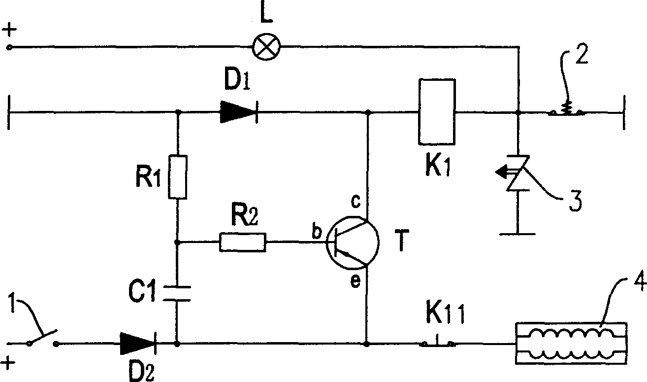
[0018] The first embodiment: as figure 1 As shown, the engine failure protection device includes an ignition coil control circuit electrically connected to the ignition switch 1, and an engine failure detection circuit; the ignition coil control circuit is connected in parallel with the engine failure detection circuit; the ignition coil control circuit includes The ignition coil 4, the engine failure detection circuit includes an engine oil pressure switch 2, and a thermal switch 3, and the engine oil pressure switch 2 and the thermal switch 3 are connected in parallel. When the oil pressure is lower than the set value, the oil pressure switch 2 is closed, and when the oil pressure is higher than the set value, the oil pressure switch 2 is disconnected. When the temperature of the coolant is higher than the set value, the thermosensitive switch 3 is closed, and when the temperature of the coolant is lower than the set value, the thermosensitive switch 3 is disconnected. The ...

Embodiment approach

[0024] This embodiment is suitable for gasoline vehicles.

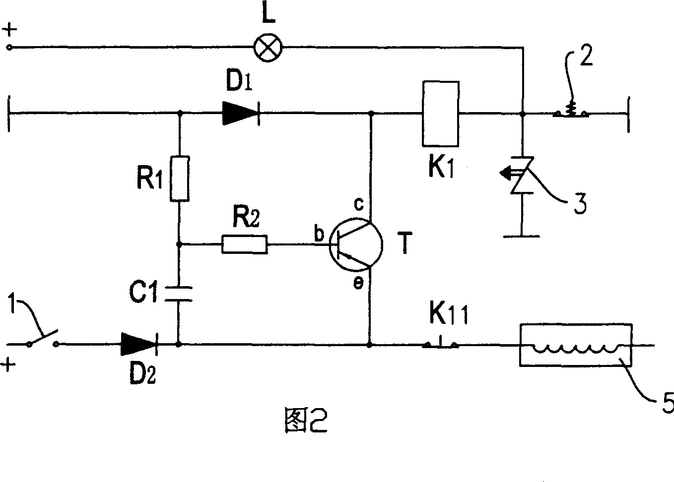
[0025] The second is the embodiment: as shown in Figure 2, its structure is basically the same as that of the first embodiment, the difference is that the ignition coil control circuit is replaced by the fuel stop solenoid valve control circuit, and the fuel stop solenoid valve control circuit includes a fuel stop Solenoid valve 5. This embodiment is suitable for diesel vehicles.

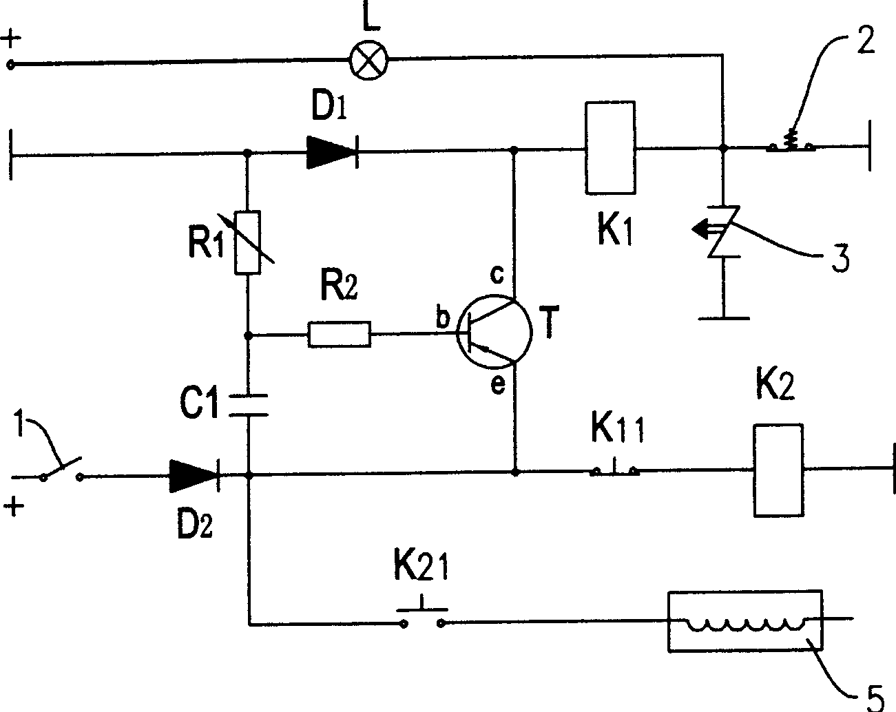
[0026] The third is the embodiment: such as image 3 As shown, its structure is basically the same as the second embodiment, and is also suitable for diesel vehicles. Since some fuel stop solenoid valves 5 need to be driven by a large current, this embodiment is designed for adapting to the fuel stop solenoid valve driven by a large current.

[0027] The difference is that the oil stop solenoid valve control circuit includes a high-current relay branch, the high-current relay branch includes a high-current relay K2, and the normally clos...


PUM


Abstract

Present invention discloses a engine trouble protector. It contains a ignition coil control circuit electric connection with ignition switch. an engine trouble sensing circuit, said ignition coil control circuit parallel connection with said engine trouble sensing circuit, said ignition coil control circuit including ignition coil, said engine trouble sensing circuit including a parallel connected mobile oil pressure switch, a thermoswitch and timing relay series connected with mobile oil pressure switch or thermoswitch, normally closed contact of said timing relay series connected with ignition coil. Said engine trouble protector has simple structure, convenient installation, and low cost, not only ensuring motor starting up but also providing mobile oil fault and high temperature fault doubling protection. Engine trouble protector not only fits gasoline motor car, also fits diesel car by replacing ignition coil control circuit with fuel cut-off solenoid valve circuit.

Description

technical field [0001] The invention relates to a protection device for an internal combustion engine, in particular to an engine failure protection device capable of automatically shutting down the engine when engine oil failure and high temperature failure occur. Background technique [0002] The engine is the main component of the car, and the engine damage caused by oil failure and high temperature failure is the main reason for the car to be overhauled in advance. Sudden failure of the oil pump, oil leakage, and blockage of the oil passage can all cause the engine to burn tiles, cylinders or cylinders, and in severe cases may even cause the engine to be scrapped. Coolant leakage, water pump or fan failure may cause the engine temperature to be too high, resulting in deformation of the cylinder block and cylinder head, cylinder scuffing and cylinder head gasket burning. Although the car is equipped with oil pressure and water temperature alarms, in normal driving, the d...

Claims


Application Information

Patent Timeline
IPC IPC(8): F01M1/26F01M11/10
Inventor 刘强
Owner 刘强
Learn More