Automatic-regualting burner for gas furnace

An automatic adjustment and burner technology, which is applied to gas fuel burners, burners, combustion methods, etc., can solve the problems of inability to adapt to changes in parameters of the combustion process, tempering and deflagration of the mixture, and poor combustion effect, and achieves simple structure, Safe to use and avoid the effect of tempering and deflagration

Inactive Publication Date: 2006-08-09
杜英玮
View PDF0 Cites 4 Cited by
  • Summary
  • Abstract
  • Description
  • Claims
  • Application Information

AI Technical Summary

Problems solved by technology

[0002] Existing gas furnace burners usually use gas and air to enter the mixing chamber from the gas source and fan through their respective air inlets. When setting the mixing ratio of gas and air in the mixing chamber, first set the gas source pressure and In the case of flow rate, the fan pressure and flow rate are selected to obtain the mixing ratio of the best combustion state. However, during the combustion process, parameters such as the amount of mixed g

Method used


Image

  • Automatic-regualting burner for gas furnace

Examples


Embodiment Construction

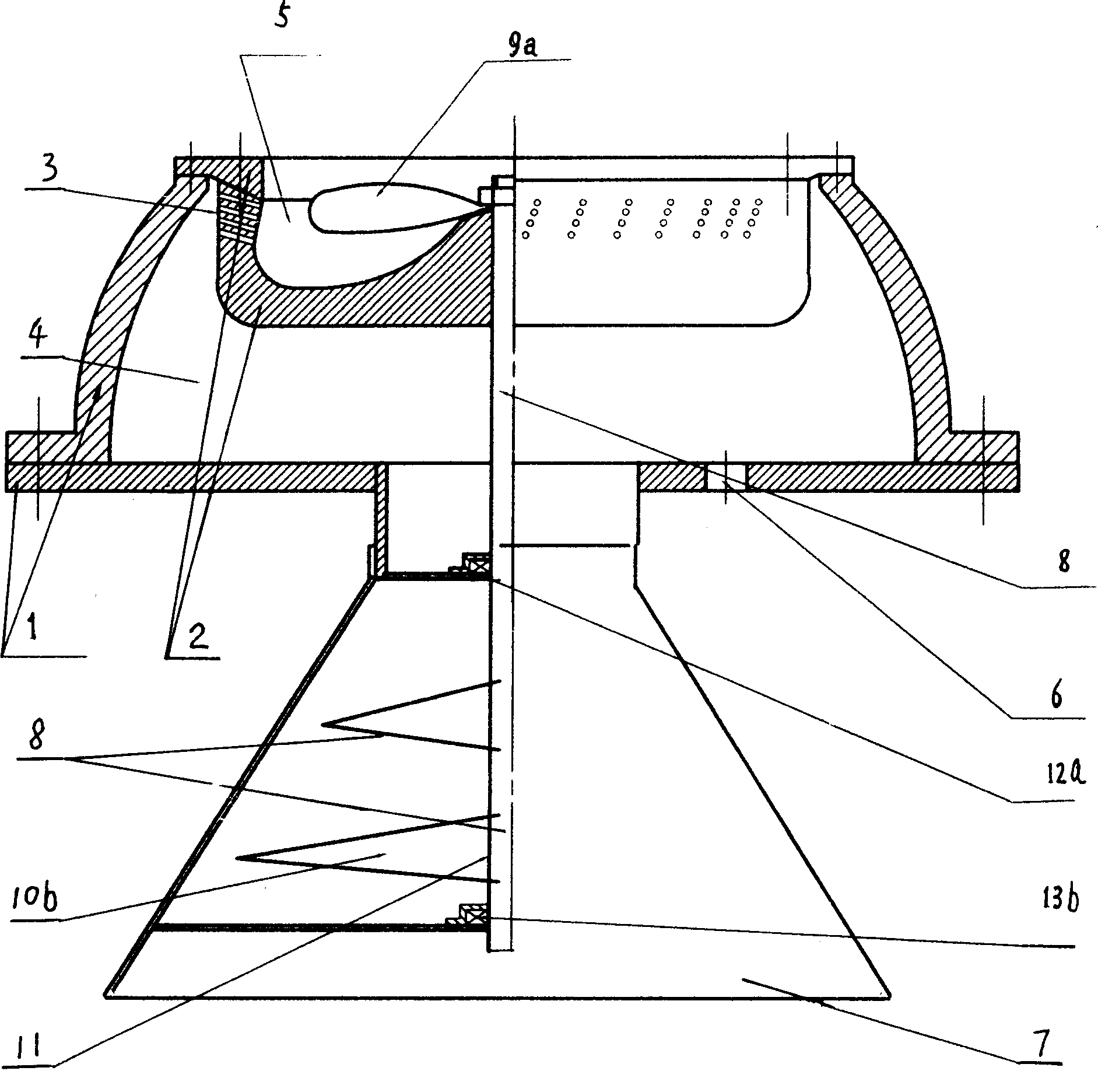
[0008] The present invention will be further described below using the embodiments shown in the accompanying drawings.

[0009] refer to figure 1 , an automatic adjustable burner for a gas furnace has a shell 1, an ejector 2, and the shell 1 and the ejector 2 are connected by screws. The cavity between the housing 1 and the injector 2 is the gas mixture chamber 4, and the cavity in the injector 2 is the combustion chamber 5. On the peripheral wall of the injector 2, there are several gas chambers communicating with the gas mixture chamber 4. A gas distribution hole 3, a gas inlet 6 and an air inlet 7 are respectively arranged at the bottom of the housing 1, and a linkage fan 8 is arranged in the combustion chamber 5 and the air inlet 7. The structure of the linked fan 8 is that it is installed on the central axis 11 of the combustion chamber 5, the mixed air chamber 4 and the air inlet 7, and is located on the two sections of the central axis 11 of the combustion chamber 5 an...


PUM


Abstract

A gas furnace self-adjustment type burner includes shell, ejector, gas mixture chamber, combustion chamber, gas distribution hole, gas inlet and air inlet. It features linkage fan set in combustion chamber and air inlet, said linkage fan set vane a and b a and b respectively on combustion chamber and air inlet central shaft. Linkage rotation is realized by thermal current impulsion of vane whose speed depending on air inlet pressure and flow rate variation, Linkage fan rotational velocity automatically controlling fuel gas with air mixing ratio in mixing chamber, therefore having good firing effect, saving fire gases, avoiding gas mixture backfire detonation combustion, safety use etc advantages.

Description

technical field [0001] The invention belongs to stove components, and is an automatic adjustable burner for a gas stove. Background technique [0002] Existing gas furnace burners usually use gas and air to enter the mixing chamber from the gas source and fan through their respective air inlets. When setting the mixing ratio of gas and air in the mixing chamber, first set the gas source pressure and In the case of flow rate, the fan pressure and flow rate are selected to obtain the mixing ratio of the best combustion state. However, during the combustion process, parameters such as the amount of mixed gas required for combustion, gas pressure and flow rate, and inlet air pressure and flow rate are changed, so , the existing gas furnace burner sends air to the mixing chamber from the blower at constant pressure and constant flow, which cannot meet the needs of changes in the parameters of the combustion process; the existing gas furnace burner has poor com...

Claims


Application Information

Patent Timeline
IPC IPC(8): F23D14/02F23D14/60
Inventor 杜英玮
Owner 杜英玮
Why Eureka
Try Eureka