Irreversible circuit element

A technology of circuit components and electrodes, which is applied in the field of non-reversible circuit components, can solve the problems of large-scale inability to adjust coupling capacitors, large capacitance values, and performance degradation, etc., and achieve the effects of cheap assembly, simple adjustment, and good operating efficiency

Inactive Publication Date: 2006-08-09
ALPS ALPINE CO LTD
View PDF0 Cites 0 Cited by
  • Summary
  • Abstract
  • Description
  • Claims
  • Application Information

AI Technical Summary

Problems solved by technology

[0007] However, since the conventional non-reciprocal circuit elements only use the first, second, and third chip capacitors C1, C2, and C3, it is necessary to make the first, second, and third central conductors 57, 58, and 59 longer. , or increase the capacitance values ​​of the first, second, and third chip-type capacitors C1, C2, and C3, which will not only increase the size but also make it impossible to adjust the coupling capacitance, resulting in a decrease in performance
[0008] Conventional non-reciprocal circuit elements only use the first, second, and third chip capacitors C1, C2, and C3, so it is necessary to make the first, second, and third center conductors 57, 58, and 59 longer, or Increasing the capacitance of the first, second, and third chip capacitors C1, C2, and C3 not only increases the size, but also makes it impossible to adjust the coupling capacitance, resulting in a problem of performance degradation

Method used


Image

  • Irreversible circuit element
  • Irreversible circuit element
  • Irreversible circuit element

Examples


Embodiment Construction

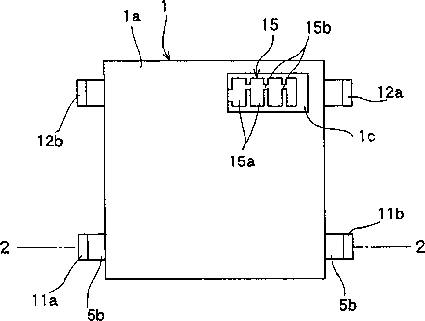
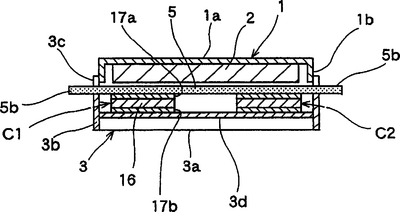
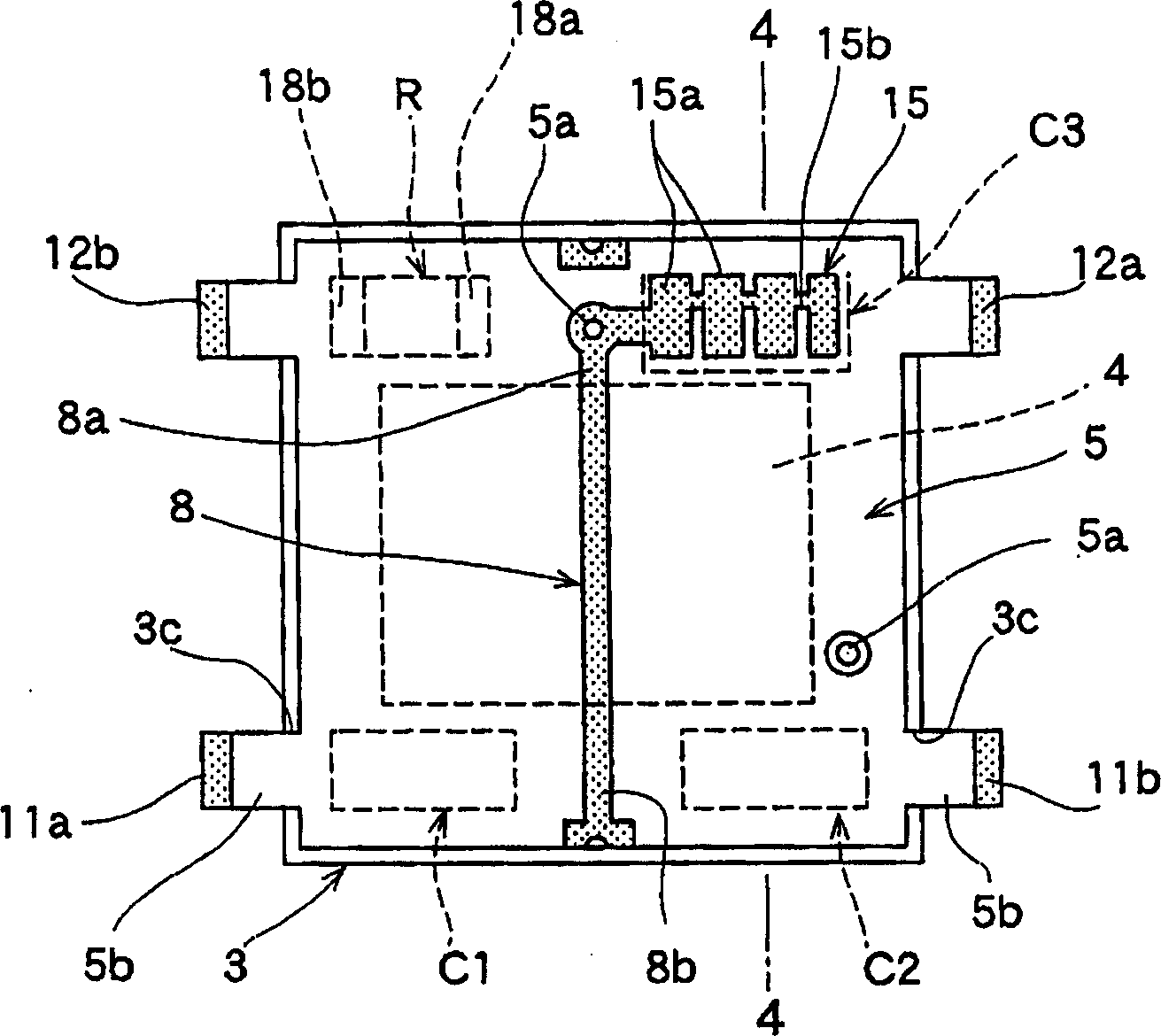
[0043] The accompanying drawings of the non-reciprocal circuit element of the present invention are described, figure 1 It is a plan view showing the first embodiment of the non-reciprocal circuit element of the present invention, figure 2 yes means figure 1 A sectional view of the 2-2 line, image 3 It is a plan view showing the state of the first embodiment of the nonreciprocal circuit element of the present invention, except for the first yoke and the magnet, Figure 4 express image 3 The profile of the 4-4 line, Figure 5 It is a bottom view showing the state in which the bottom plate of the second yoke is removed of the first embodiment of the non-reciprocal circuit element of the present invention.

[0044] in addition, Figure 6 It is a bottom view showing the multilayer substrate of the first embodiment of the nonreciprocal circuit element of the present invention, Figure 7 It is a bottom view showing the first embodiment of the non-reciprocal circuit elemen...


PUM


Abstract

To provide a nonreciprocal circuit element which is small and has excellent performance. In this nonreciprocal circuit element, first, second, third center conductors 6, 7, 8 are provided in a multilayer substrate 5, first and second electrodes 14 and 15 forming a first capacitor C4 are provided in the multilayer substrate 5, a plurality of chip capacitors C1, C2, C3 are provided between port sections 6a, 7a, 8a of the center conductors 6, 7, 8 and a yoke 3, and the first capacitor C4 and chip type capacitors C1, C2, C3 are connected in series between the port sections 6a, 7a, 8a and the yoke 3. With this configuration, capacitance value can be made large, the length of each of the center conductors can be shortened and miniaturization can be realized, the first capacitor C4 can be easily formed, and an inexpensive element having good productivity can be obtained.

Description

technical field [0001] The present invention relates to a non-reciprocal circuit element composed of an isolator or a circulator suitable for an antenna duplexer or a mobile communication device. Background technique [0002] Figure 14 is an exploded perspective view showing a conventional non-reciprocal circuit element, Figure 15 is a cross-sectional view showing a main part of a conventional nonreciprocal circuit element, and then, based on Figure 14 , Figure 15 The structure of the conventional non-reciprocal circuit element will be described. A box-shaped first yoke 51 and a U-shaped second yoke 52 are coupled to each other to form a closed magnetic circuit. [0003] The insulating substrate 53 accommodated in the second yoke 52 is provided with a circular hole 53a provided in the center and a plurality of rectangular holes 53b provided in the outer periphery of the circular hole 53a. There are a plurality of ground patterns 54 , and the ground patterns 54 are conn...

Claims


Application Information

Patent Timeline
Patent Type & Authority Applications(China)
IPC IPC(8): H01P1/36
Inventor 石垣功清水祐一高野敦雄须藤义人柴山贵光
Owner ALPS ALPINE CO LTD
Why Eureka
Try Eureka