Method and apparatus for aligning magnetizable particles in a pasty material

A paste-like, particle-based technology, applied in the field of devices and methods for orienting magnetizable particles in paste-like materials, capable of solving problems such as release reduction layer structure quality, not optimal fiber orientation, irregular orientation, etc.

Inactive Publication Date: 2006-08-09
BAKKER HLDG SON
View PDF2 Cites 13 Cited by
  • Summary
  • Abstract
  • Description
  • Claims
  • Application Information

AI Technical Summary

Problems solved by technology

[0007] A disadvantage of the described device or of the method carried out with the device is that only fibers adjacent to the device can be oriented, so that other distant fibers retain their irregular orientation
And due to the higher residual magnetic field strength at the release position the orientation of the fibers is not optimal
Although the range of the magnetic field can be increased to a limited extent by simply increasing the magnetic field strength with stronger magnets, the quality of the layer structure is significantly reduced due to poor release of oriented particles

Method used


Image

  • Method and apparatus for aligning magnetizable particles in a pasty material
  • Method and apparatus for aligning magnetizable particles in a pasty material
  • Method and apparatus for aligning magnetizable particles in a pasty material

Examples


Embodiment Construction

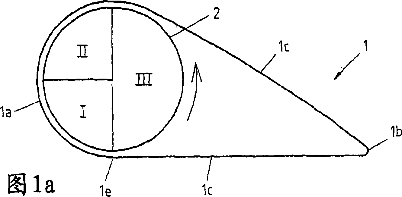
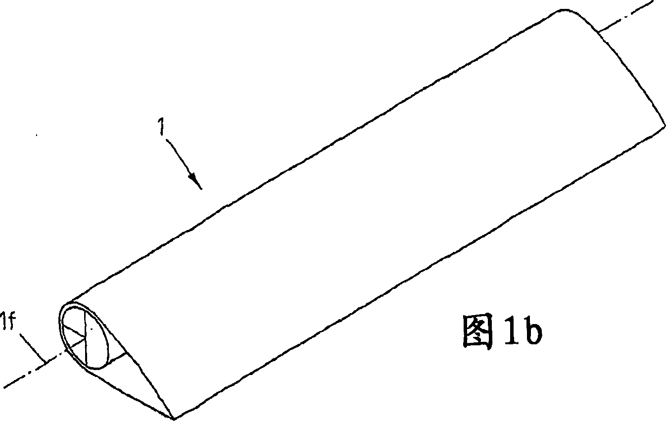
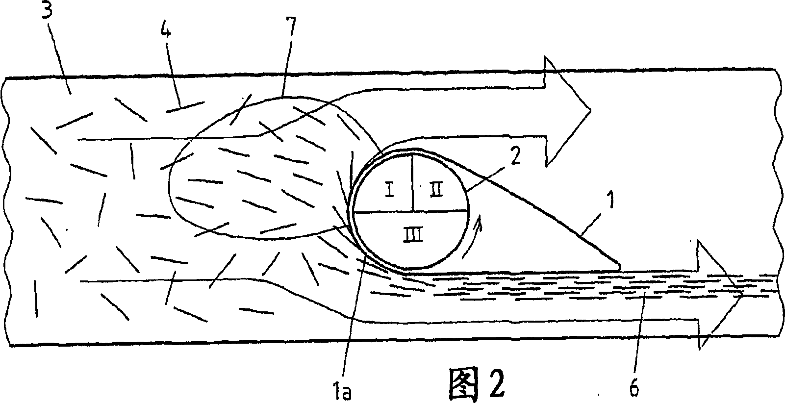
[0036] A device for orienting magnetizable particles in a pasty material is shown in FIGS. 1 a and 1 b. The device has an orienting body 1 in the form of a hollow profile, which consists of a non-magnetic material. According to the cross-sectional view in FIG. 1 a , the hollow profile comprises a circular arc-shaped front part 1 a which tapers in a straight line via two side parts 1 c in the direction of a rear surface part 1 b. Inside the orienting body 1 is arranged a magnet arrangement 2, which is configured as a cylindrical roller mounted on a rotatable support concentrically with respect to the arc-shaped front surface portion 1a. The magnet roller 2 is equipped with permanent magnets along its longitudinal axis and is rotated, for example, by one or more electric motors (not shown). Thus a rotating, i.e. periodically varying, magnetic field acting on the particles contained in the pasty material is produced, which is divided into three regions I, II, III with partial fi...


PUM


Abstract

The invention relates to a method and device for orienting magnetisable particles (4) in a kneadable material (3), in particular steel fibres or rings in unhardened concrete by means of an orienting body (1) provided with a non-magnetic wall comprising a front face section (1a) and a rear face section (1b). A kneadable material (33) and the front face section (1a) of the orientation body (1) are first and foremost displaced with respect to each other. The orientation body (1) is also provided with a magnetic unit (2) which is disposed on the internal side of said front face section (1a) and generates a periodically variable magnetic field acting on the kneadable material in order to orient the magnetisable particles (4). Said invention is characterised in that said magnetic field is divided into at least two areas (I II) containing the partial fields exhibiting different forces and / or different directions of force lines. The partial field of the first area (I) applies long trajectory orientation and attractive forces on the particles, the partial field of the second area (II) releasing orientedly positioned particles.

Description

technical field [0001] The invention relates to a device for orienting magnetizable particles in a pasty material, comprising an orienting body having a wall comprising a front surface part and a rear surface part, wherein the pasty material and The orienting body can move relative to each other at the front with its front surface part, and the orienting body also has a magnet device arranged on the inner surface of the front surface part in the orienting body, and the magnet device produces a periodic change acting on the pasty material. A magnetic field for orienting the magnetizable particles. The invention also relates to a method for orienting magnetizable particles in a pasty material. Background technique [0002] The use of steel fibers in concrete to strengthen it has been known for about 20 years. Wherein the steel fibers are uniformly distributed in random orientation along its volume in the concrete. In a bent concrete slab, for example, it is desirable that t...

Claims


Application Information

Patent Timeline
Patent Type & Authority Applications(China)
IPC IPC(8): B28B1/52
Inventor 章顺力
Owner BAKKER HLDG SON
Why Eureka
Try Eureka