Composite microdisplacement oil jetter of IC engine with piezoelectric control

A technology of fuel injectors and internal combustion engines, which is applied in the direction of machines/engines, fuel injection devices, mechanical equipment, etc., and can solve problems such as difficulty in forming a homogeneous mixture, achieve reduced HC and NOx emissions, high control accuracy, and increase compression ratio Effect

Inactive Publication Date: 2006-08-16
侯德洋
View PDF1 Cites 8 Cited by
  • Summary
  • Abstract
  • Description
  • Claims
  • Application Information

AI Technical Summary

Problems solved by technology

For porous spray, it is difficult to form a homogeneous mixture without proper air flow coordination

Method used


Image

  • Composite microdisplacement oil jetter of IC engine with piezoelectric control
  • Composite microdisplacement oil jetter of IC engine with piezoelectric control
  • Composite microdisplacement oil jetter of IC engine with piezoelectric control

Examples


Embodiment Construction

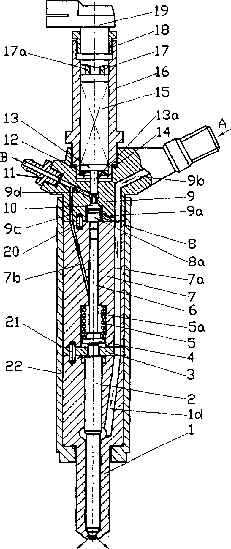
[0022] exist figure 1 , In the embodiment shown in 2, the fuel injector body consists of an upper body 16, a middle body 9 and a lower body 22 which are screwed together, and the upper body 16 is sequentially equipped with a disc spring 12, a piston with a piston rod 13a 13 and piezoelectric stack 15, piezoelectric stack 15 is electrically connected with electric socket 19 by lead wire 117 and lead wire 217a, and parts such as piezoelectric stack 15 are fastened in upper body 16 by compression sleeve 18. When upper body 16 is installed on middle body 9, seal gasket 14 should be added, and piston rod 13a should be movably inserted in the corresponding hole of middle body 9.

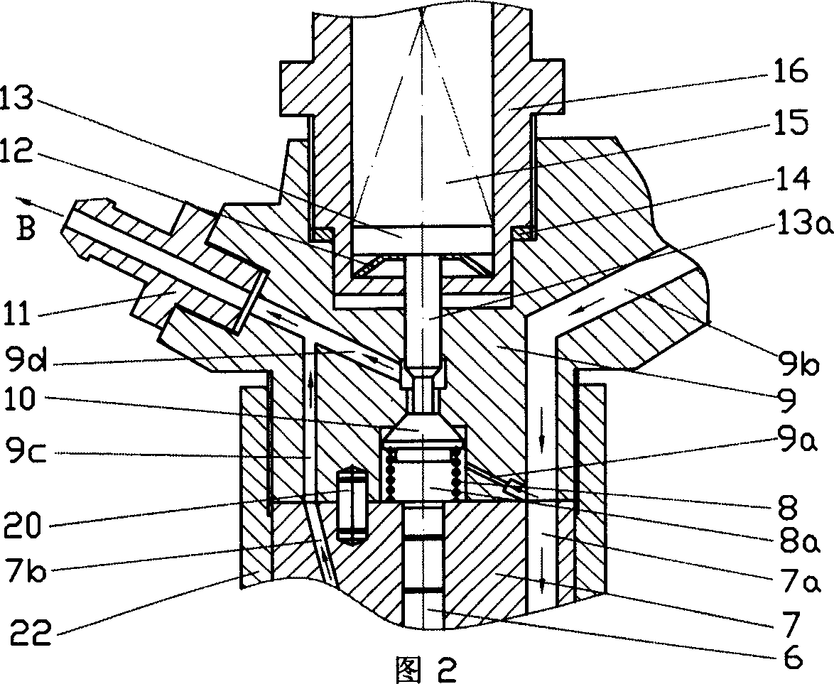
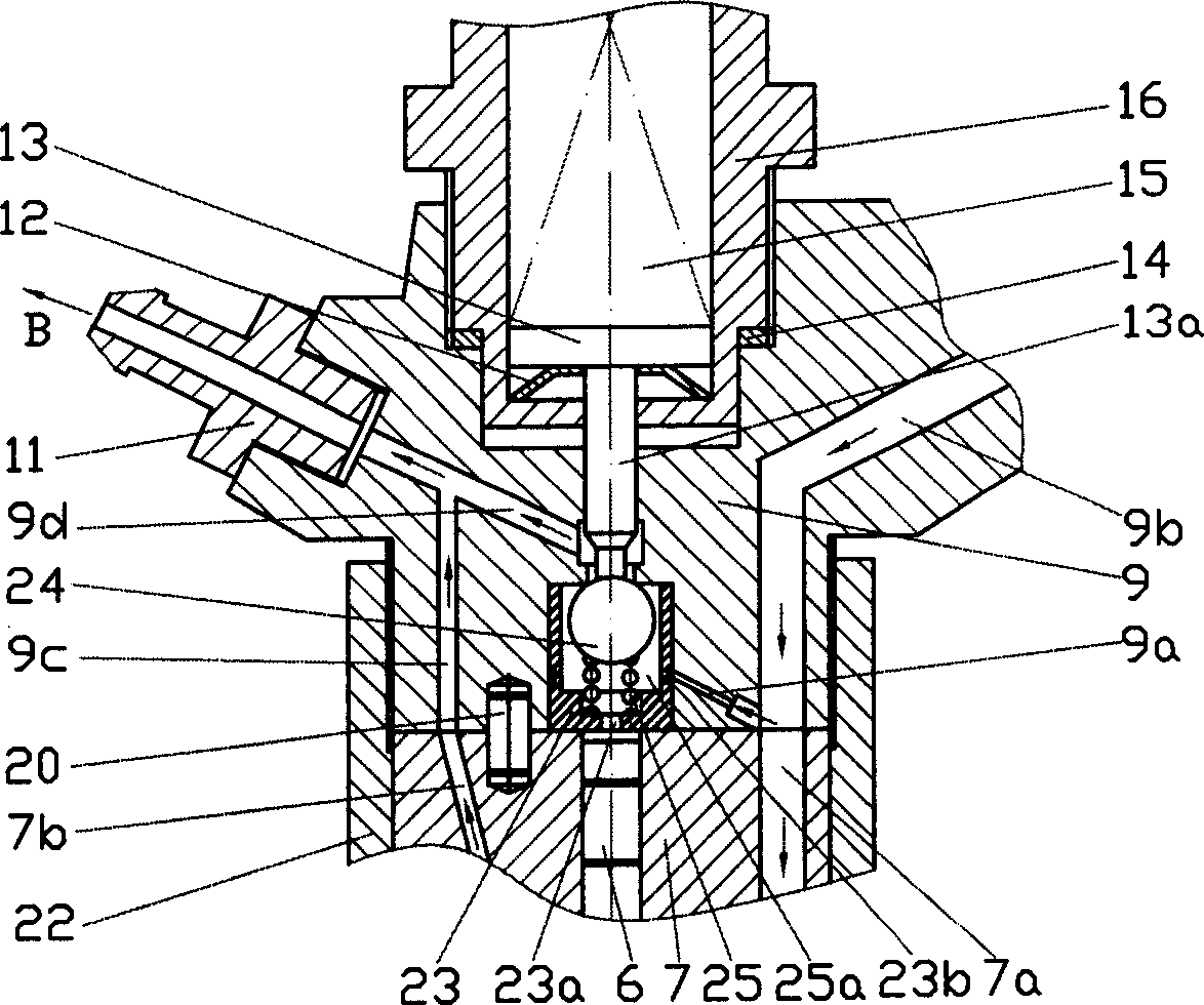
[0023] The middle body 9 is provided with a high-pressure oil inlet A, a high-pressure oil inlet passage 9b, a small high-pressure oil passage 9a and a high-pressure oil chamber 8a, as well as an oil return passage 19c, an oil return passage 29d, an oil return joint 11 and an oil return port B. There is a...


PUM


Abstract

The piezoelectric-controlled micro-displacement combined fuel injector for internal combustion engines belongs to a fuel-injector apparatus for the fuel system of internal combustion engines. Because of being controlled by a piezoelectric element, its fuel-injection correct time is easy to regulate. An internal tapered angle 2 alpha being offset from beta angle is disposed at the outlet of a fuel nozzle. An oil-guide slot is opened on an umbrella-injection internal tapered surface in order to control the appointed area where the oil beam can reach the combustion chamber easily.

Description

technical field [0001] The invention relates to a micro-displacement composite fuel injector for an internal combustion engine controlled by piezoelectricity, which belongs to the fuel injection device of the fuel system of the internal combustion engine. Background technique [0002] At present, most of the fuel injectors that inject fuel into the combustion chamber in the common rail fuel system of internal combustion engines use solenoid valves to control the back pressure acting on the needle valve of the fuel injector. When the back pressure acting on the needle valve is high, the fuel injector does not spray oil; when the back pressure acting on the needle valve is low, the high-pressure oil moves the needle valve up, and the fuel injector injects oil. In recent years, it has been a common method to control the back pressure acting on the needle valve of the injector by using the expansion or contraction deformation of the piezoelectric material when it is electrified,...

Claims


Application Information

Patent Timeline
Patent Type & Authority Applications(China)
IPC IPC(8): F02M51/06
Inventor 侯德洋
Owner 侯德洋
Why Eureka
Try Eureka