Image coding apparatus and image coding method

An image coding and coding technology, applied in the direction of image communication, television, electrical components, etc., can solve the problem that the processing speed cannot be improved, reduce the operation amount, etc., and achieve the effect of reducing the processing operation amount and realizing the processing speed.

Inactive Publication Date: 2006-08-16
PANASONIC CORP
View PDF2 Cites 20 Cited by
  • Summary
  • Abstract
  • Description
  • Claims
  • Application Information

AI Technical Summary

Problems solved by technology

However, using this conventional technique does not substantially reduce the amount of operations, and there is

Method used


Image

  • Image coding apparatus and image coding method
  • Image coding apparatus and image coding method
  • Image coding apparatus and image coding method

Examples


no. 1 example

[0038] A first embodiment of the present invention will be described below with reference to the drawings.

[0039] Figure 4It is a block diagram showing the overall configuration of the image encoding device 1 of the present invention. The image coding device 1 is a device for performing intra prediction of the present invention, and the image coding device 1 includes an intra prediction unit 11, a difference calculation unit 12, a switch 13, an orthogonal transformation unit 14, a quantization unit 15, an entropy coding unit 16. An inter prediction unit 17 and an encoding control unit 18 for performing inter prediction. The inter prediction unit 17 has a switch 170 , an inverse quantization unit 171 , an inverse transform unit 172 , an adder 173 , a loop filter 174 , a frame memory 175 , a motion prediction unit 176 , and a motion compensation unit 177 .

[0040] When inter prediction is performed, information on the current frame to be encoded is input to the difference ...

no. 2 example

[0081] A second embodiment of the present invention will be described below with reference to the drawings.

[0082] The overall configuration of the image encoding device 1 of the second embodiment is similar to Figure 4 The first embodiment shown is the same, so its description will not be contained here.

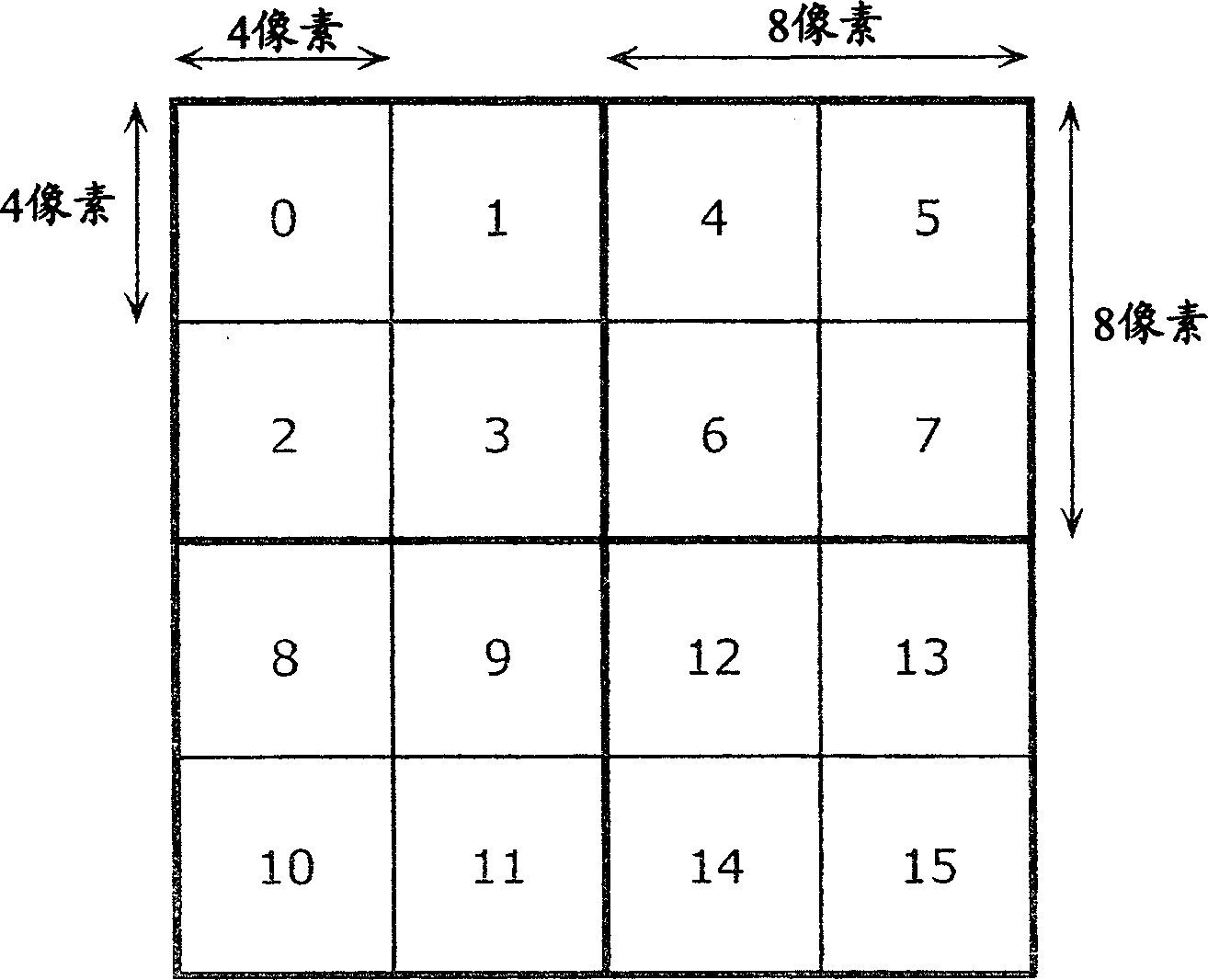
[0083] Figure 16 is a block diagram showing the configuration of the intra prediction unit of the second embodiment of the present invention. The intra prediction unit 11 calculates prediction errors for 8×8 blocks in 16×16 macroblocks by skipping some pixels, and determines the intra prediction mode for 4×4 blocks in 8×8 blocks. The intra prediction unit 11 includes a pixel selection unit 61 , a mode error value calculation unit 42 , an inter-mode comparison unit 43 , and a block prediction value calculation unit 62 .

[0084] Here the prediction error calculation unit corresponds to the block prediction value calculation unit 62 , and the macroblock mode determinat...


PUM


Abstract

The image coding apparatus does not determine the intra-frame prediction mode based on the prediction error of the entire blocks included in a macro block, but executes intra-frame prediction with the predetermined intra-frame prediction mode for a certain block. The block selection unit judges that the current block to be coded is a prediction error calculation block or a non-prediction error calculation block. In the case where the current block is a prediction error calculation block, the mode error value calculation unit calculates the prediction error by the sum of absolute differences and the like for all of the intra-frame prediction modes, the inter-mode comparison unit compares the prediction errors, and as a result of the comparison, the intra-frame prediction mode having the minimum prediction errors is determined as the intra-frame prediction mode. In the case where the current block is a non-prediction error calculation block, the prediction error is not calculated. As an alternative method the prediction mode estimation unit determines the intra-frame prediction mode based on the neighboring prediction mode information stored in the storage unit.

Description

technical field [0001] The present invention relates to the encoding technology of moving pictures. More specifically, the present invention relates to a technique for efficiently selecting an intra prediction mode from a plurality of intra prediction modes in the moving image coding defined by the H.264 standard to reduce the amount of operations required for encoding a moving image. technology. Background technique [0002] In recent years, digitization of AV information has made great progress, and devices capable of processing digitized video signals have also been popularized. Incidentally, a video signal contains a large amount of information, so it is more necessary to encode the video signal by reducing the amount of information in consideration of storage capacity and transmission efficiency. The international standard H.264 is used as the standard of image signal coding technology. In the H.264 standard, intra prediction is introduced to perform prediction withi...

Claims


Application Information

Patent Timeline
IPC IPC(8): H04N7/32H04N19/11
Inventor 有村耕治荒川博田坂启增野贵司
Owner PANASONIC CORP
Why Eureka
Try Eureka