Open-phase detecting method of three-phase transformer

A three-phase converter, power supply phase loss technology, applied in multi-phase network asymmetric measurement, instruments, electrical components and other directions, can solve the problems of complex hardware structure, increased cost, increased CPU load, etc., to reduce the number of IRQs, The effect of reducing the possibility and reducing the load on the CPU

Inactive Publication Date: 2006-08-23
YASKAWA DENKI KK
View PDF2 Cites 17 Cited by
  • Summary
  • Abstract
  • Description
  • Claims
  • Application Information

AI Technical Summary

Problems solved by technology

[0009] Using the power supply phase loss detection method in the previous example 1 needs to set the neutral point and calculate the two phases, so there is a problem that the hardware structure is complicated and the cost increases
In addition, there is also the problem that the detection error cannot be denied because only the phase difference is used to judge the phase loss.
Furthermore, there is also the problem of increased CPU load due to the use of two IRQs

Method used


Image

  • Open-phase detecting method of three-phase transformer
  • Open-phase detecting method of three-phase transformer
  • Open-phase detecting method of three-phase transformer

Examples


Embodiment 1

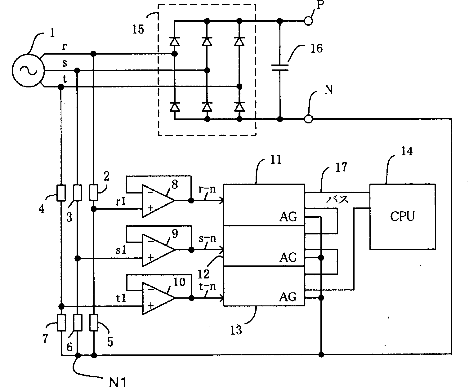
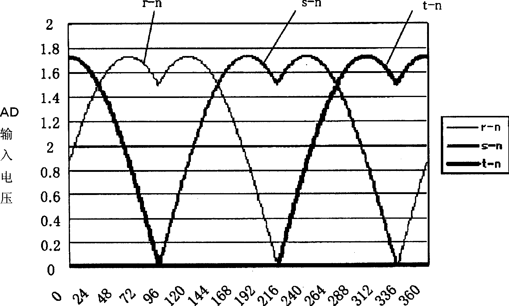
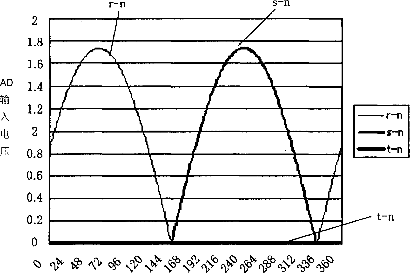
[0065] Fig. 1 is an embodiment of a three-phase converter applying the method of the present invention. Figure 2 is the AD input voltage when it is normal, Figure 3 is the AD input voltage when the T phase is open, Figure 4 is the power supply voltage when it is normal, Figure 5 is the power supply voltage when the T phase is open, and Figure 6 is the normal time Line voltage, Figure 7 is the line voltage when the T phase is open, Figure 8 is the DC bus N terminal voltage when it is normal, and Figure 9 is the DC bus N terminal voltage when the T phase is open.

[0066]In FIG. 1, 1 is a three-phase AC power supply, 2 is a first resistor for dividing r-phase voltage, and 5 is a second resistor for dividing r-phase voltage. The s-phase and t-phase are the same as the r-phase, respectively having the first resistor 3 and the second resistor 6 for dividing the voltage of the s-phase and the first resistor 4 and the second resistor 7 for dividing the voltage of the t-phase. 8-10 ar...


PUM


Abstract

An open-phase detecting method wherein a simple hardware structure is used to achieve a reduced cost: the IRQ member is reduced to reduce the load on a CPU; the open phase detection is performed in two items, that is, a phase difference and a voltage sign to reduce the possibility of occurrence of erroneous detections; and any phase that is open can be also determined. In the method for detecting any open-phase of the power supply of a three-phase converter, a neutral point N1 is connected to a negative pole side bus N of the DC side output of the rectifying means; an end of the first resistor of each phase, which connects the first resistor to the second resistor of each phase, is connected to an AD converter via a high input impedance means of the respective phase to detect the voltage of the respective phase; the voltage of the respective phase is outputted to a CPU that serves as an open-phase detecting means; and an open phase is detected when the sings of two of the three line voltages determined based on the voltages of the respective phases are different from each other and a phase difference thereof exhibits a half-wave rectification waveform of 180 DEG .

Description

technical field [0001] The invention relates to a power supply phase loss detection method for a three-phase converter. Background technique [0002] In the past, the power supply phase loss detection method of the three-phase converter is to compare the analog neutral point of the three-phase AC power supply with the input voltage, input the generated logic signal into the counter, and detect the phase difference of each phase. When the phase difference deviates from the specified value, it is judged as phase loss. [0003] A configuration diagram of this conventional example is shown in FIG. 10 (Japanese Patent Application Laid-Open No. 2003-235154: hereinafter referred to as conventional example 1). In Fig. 10, the midpoint of each phase of the three-phase AC power supply r, s, and t connected in star form by resistors 55 to 60 is taken as the simulated neutral point N1, and the voltage of r and s viewed from the simulated neutral point N1 is taken as R1 , S1 to detect....

Claims


Application Information

Patent Timeline
Patent Type & Authority Applications(China)
IPC IPC(8): G01R29/18G01R19/165G01R19/155G01R29/16G05F1/10H02H3/253H02H3/34
CPCG01R29/16
Inventor 平松和彦高桥肇
Owner YASKAWA DENKI KK
Why Eureka
Try Eureka