
Laser beam scanner

A technology of laser beams and scanners, applied in optics, instruments, optical components, etc., can solve problems such as expensive packaging steps, low resonance frequency, and small projection display

Inactive Publication Date: 2006-08-23
KONINKLIJKE PHILIPS ELECTRONICS NV
View PDF3 Cites 17 Cited by
  • Summary
  • Abstract
  • Description
  • Claims
  • Application Information

AI Technical Summary

Problems solved by technology

However, for a rigid cantilever or torsion bar, the optical scan angle of the mirror is typically around 5 degrees, which is too small for projection displays for close range applications
In addition, these scanners operate in a vacuum to avoid air damping, requiring expensive packaging steps
With weaker torsion bars or cantilevers, the optical scan angle can be increased, but at the same time the resonant frequency is too low for scanning at image speeds suitable for video applications

Method used


Image

  • Laser beam scanner
  • Laser beam scanner
  • Laser beam scanner

Examples


Embodiment Construction

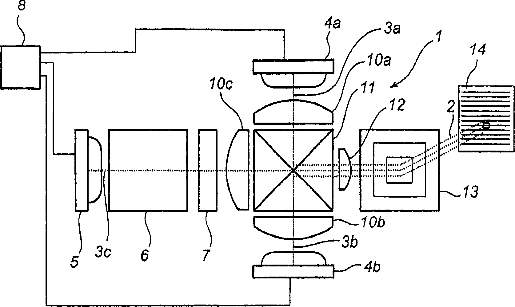
[0024] figure 1 It is a schematic diagram of a scanner projection device 1 implementing the present invention. The device is capable of projecting a laser beam 2 onto a surface (eg a wall, not shown) and is sized for mobile applications such as a mobile phone or PDA. This means that the size is generally on the order of 10mm*10mm.

[0025] exist figure 1 In the shown projection device 1, the desired color is obtained by combining the red, blue and green laser beams 3a, 3b, 3c in a ratio determined by the video signal. Then let the combined laser beam 2 shoot to the scanning device 13, and scan on the screen 14 to obtain a color image.

[0026] The red and blue laser beams are preferably generated by means of laser diodes 4a, 4b emitting light in the red and blue wavelength regions, respectively. While red and blue laser diodes are commercially available, green diodes are not currently available (though expected to be in the future). Thus in the projector shown, green ligh...


PUM


Abstract

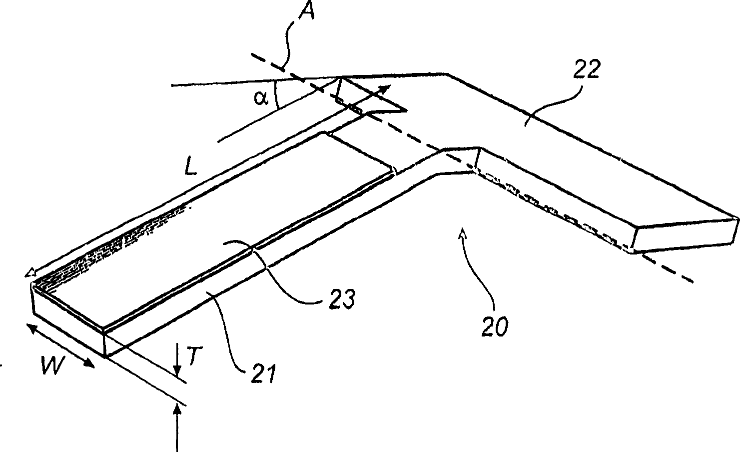
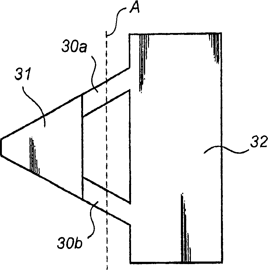
A two dimensional scanning device, for use in a projecting display, comprising a surface (53) suspended by at least two torsion elements (55) defining a torsion axis (B), and a first actuator (60, 61) for pivoting said surface (53) around said torsion axis (B). The scanner further comprises a cantilever beam (51) having one end fixed in relation to said surface and an opposite end arranged to bend around a bending axis (A) non-parallel to said torsion axis (B). The cantilever beam (51) is provided with a reflective surface and a second actuator (58) is arranged to bring said cantilever beam to oscillate at its resonance frequency. The combination of a slow torsion scanner and a faster cantilever scanner 10 provides a two dimensional scanner capable of scanning a laser beam in a raster pattern to project an image.

Description

technical field [0001] The invention relates to a two-dimensional scanning device for projection display comprising a surface suspended by at least two torsion elements defining a torsion axis, and a first actuator for rotating the surface about the torsion axis. Background technique [0002] Recently it has been proposed to develop small hand-held electronic devices, such as mobile phones or PDAs, with image projectors. This ability to display information on a much larger display area than current monitors will pave the way for activities such as watching live video, playing games and sharing images. [0003] Such projection display devices must be small, inexpensive, lightweight, consume little power and be robust. In order to display video information, the image refresh rate must be higher than or equal to 50Hz. The line frequency is related to the image speed, the number of display lines, and whether the image is progressive or interlaced. A rough estimate of the requ...

Claims


Application Information

Patent Timeline
IPC IPC(8): G02B26/08G02B26/10
CPCG02B26/0833G02B26/101G02B26/0841G02B26/0866G02B26/085G02B26/0858G02B26/08G02B26/00
Inventor O·H·威伦森A·H·M·霍尔特斯拉W·L·伊扎曼S·T·德兹瓦特
Owner KONINKLIJKE PHILIPS ELECTRONICS NV
Learn More