Light emitting diode (led) driver

A light-emitting diode and driver technology, which is applied in electroluminescent light sources, instruments, light sources, etc., can solve the problems of accelerating LED degradation and reducing light efficiency

Inactive Publication Date: 2006-08-30
SAMSUNG ELECTRONICS CO LTD
View PDF1 Cites 5 Cited by
  • Summary
  • Abstract
  • Description
  • Claims
  • Application Information

AI Technical Summary

Problems solved by technology

Since the reverse recovery current flows through the LED module 210, it will accelerate the deterioration of the LED
In addition, the DMD module is not turned off until the reverse recovery current disappears and the circuit is stable, reducing the light efficiency

Method used


Image

  • Light emitting diode (led) driver
  • Light emitting diode (led) driver
  • Light emitting diode (led) driver

Examples


Embodiment Construction

[0031] Reference will now be made in detail to embodiments of the invention, examples of which are illustrated in the accompanying drawings, wherein like reference numerals refer to like elements throughout. The embodiments are described below in order to explain the present invention by referring to the figures. Figure 4 The structure of the LED driver 10 according to the exemplary embodiment of the present invention is shown.

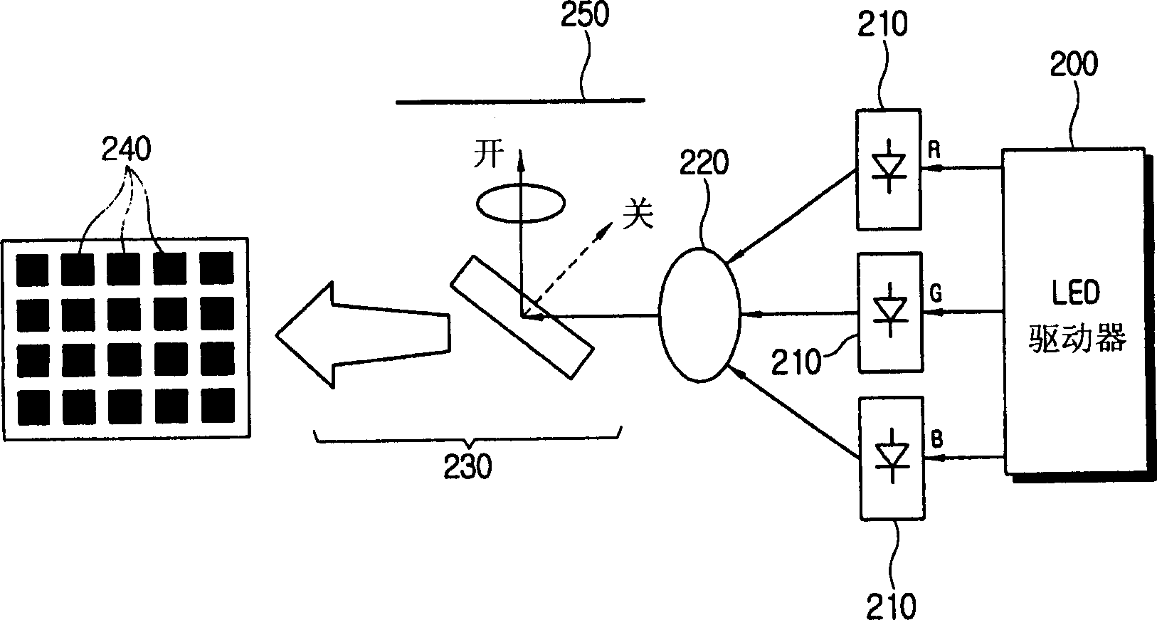
[0032]The LED driver 10 of this embodiment drives a plurality of LEDs 30 used as LCD backlights and light sources of DMD display devices using digital micromirror devices (DMDs), such as digital light processing (DLP) projection TVs, projectors, etc. .

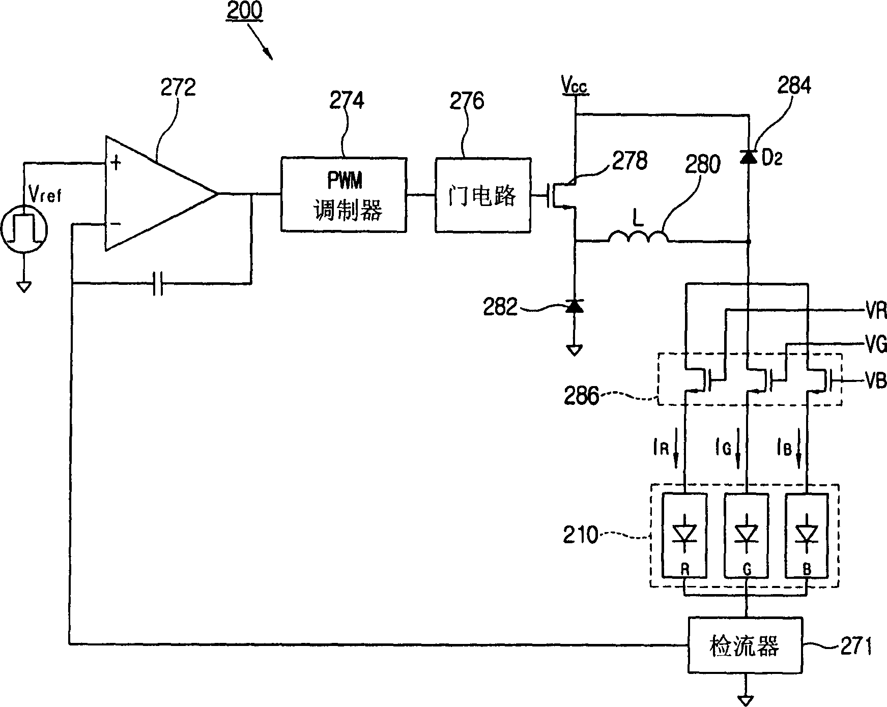
[0033] Such as Figure 4 As shown, LED driver 10 includes a current controller 12 , a plurality of divergence switches 14 and a divergence switch controller 18 . The plurality of diverging switches 14 of this embodiment are located between the current controller 12 and the anodes of the plurality ...


PUM


Abstract

An LED driver is provided for driving a plurality of light emitting diodes (LEDs), having a current controller to control a power supply of a predetermined power source unit to establish a current in the plurality of LEDs at a predetermined target current value and which sequentially changes corresponding to the respective LEDs, a plurality of divergence switches to allow flow or interrupt flow of the current with respect to each of the plurality of LEDs, and a divergence switch controller to sequentially open and close the plurality of divergence switches corresponding to changes of the target current value to make one of the plurality of divergence switches turn on before another one of the plurality of divergence switches is turned off. Thus, the LED driver has high light efficiency and excellent circuit stability without electromagnetic interference (EMI).

Description

[0001] This application claims the benefit of Korean Patent Application No. 10-2005-0016208 filed in the Korean Intellectual Property Office on February 26, 2005, the entire disclosure of which is hereby incorporated by reference. technical field [0002] The present invention relates to a light emitting diode (LED) driver. More particularly, the present invention relates to an LED driver for driving light emitting diodes with high light efficiency and improved circuit stability. Background technique [0003] Light-emitting diodes (LEDs) are commonly used as light sources for liquid crystal display (LCD) devices and digital micromirror device (DMD) display devices using digital micromirror devices (DMD), such as digital light processing (DLP) Projection TV, projector, etc. [0004] figure 1 A DMD display device employing LEDs as light sources is shown. This DMD display device uses a plurality of LED modules 210 corresponding...

Claims


Application Information

Patent Timeline
Patent Type & Authority Applications(China)
IPC IPC(8): H05B33/08H05B37/00H05B44/00
CPCH05B33/0818Y02B20/347H05B33/086H05B33/0815H05B45/20Y02B20/30H05B45/3725G01F15/068G09F9/33G01D13/12G01D15/14G01D1/18
Inventor 金湳寅
Owner SAMSUNG ELECTRONICS CO LTD
Why Eureka
Try Eureka