Wearable electronic device, method for manufacturing portable device, and portable device

A technology for electronic instruments and manufacturing methods, applied in electronic timers, instrument parts, electronic timer structural details and other directions, can solve the problems of deformation, prolapse of pads, and inability to obtain a sealed state, so as to improve the yield and reduce The effect of manufacturing cost

Inactive Publication Date: 2006-09-06
SEIKO EPSON CORP
View PDF2 Cites 27 Cited by
  • Summary
  • Abstract
  • Description
  • Claims
  • Application Information

AI Technical Summary

Problems solved by technology

In this case, if the range of the center angle of the two shells is small, there will be no problem, but if the range of the center angle of the two shells is large, when the two shells overlap, the surface near the end of the shell will be damaged. There is a problem that a normal airtight state cannot be obtained because the spacer near the end is deformed due to stress in the direction of bending on the surface or inside, or falls out of the spacer case due to friction between them.

Method used


Image

  • Wearable electronic device, method for manufacturing portable device, and portable device
  • Wearable electronic device, method for manufacturing portable device, and portable device
  • Wearable electronic device, method for manufacturing portable device, and portable device

Examples


no. 1 approach

[0060] In this embodiment, an arm-worn electronic device as one form of a portable device will be described.

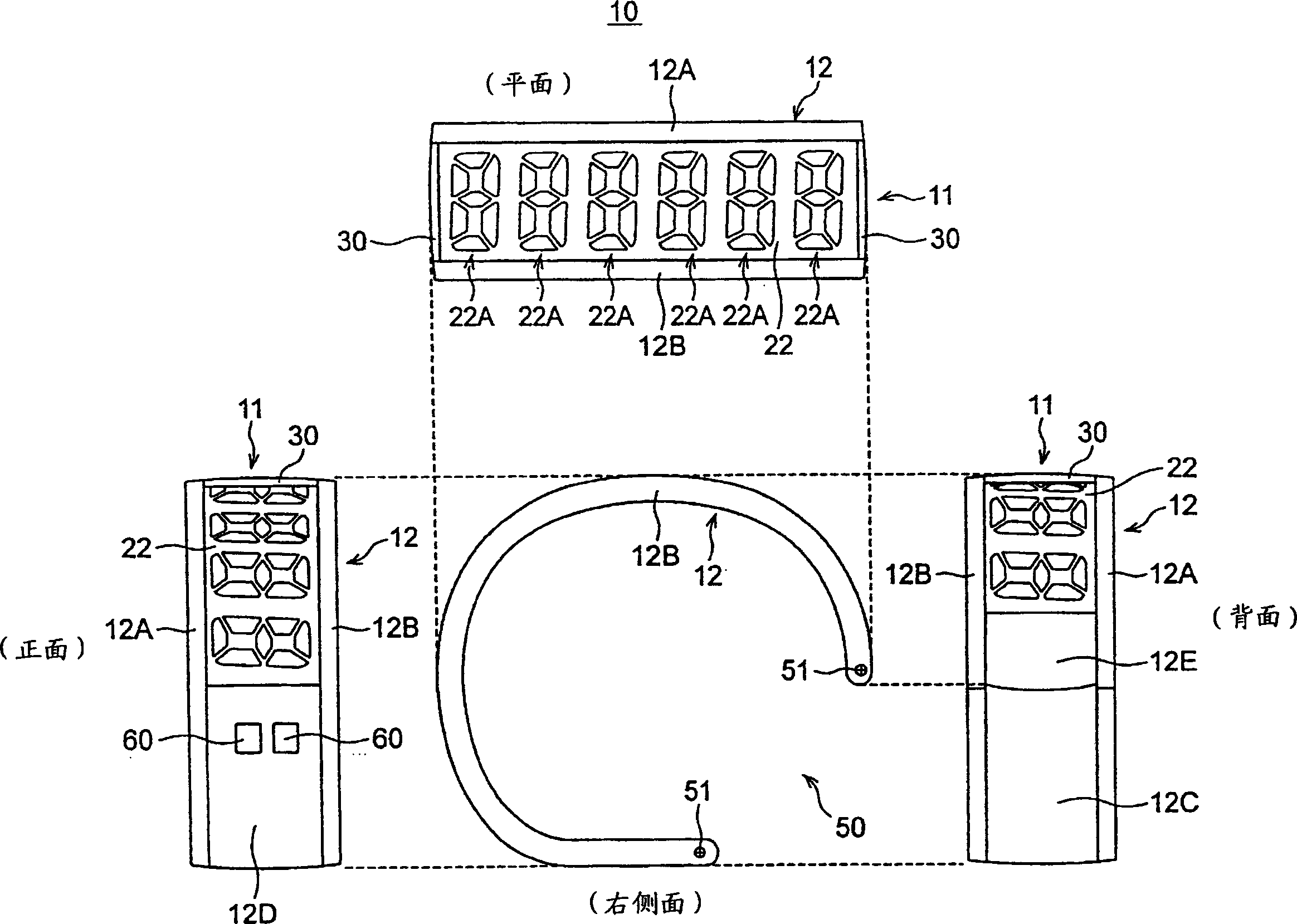
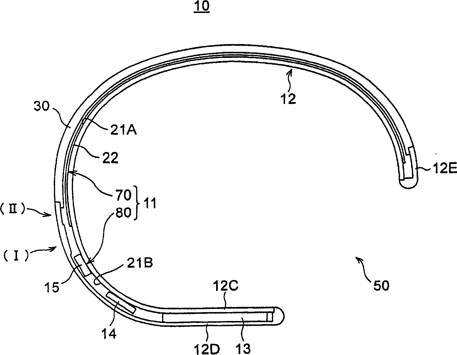
[0061] figure 1 It is a four-sided view showing the right side, the plane, the front, and the back of the arm-worn electronic device 10 of this embodiment, figure 2 It is a sectional view of the arm-worn electronic device 10 . As shown in the figure, an arm-worn electronic device 10 has a display unit 11 and a housing 12 .

[0062] Such as figure 1 and figure 2 As shown, the frame body 12 is formed in a substantially C-shaped cross section, has a separation part 50 for inserting an arm or a wrist, etc. when worn, and includes a left side frame body 12A, a right side frame body 12B, an inner cover 12C, and an exterior body. 12D, 12E.

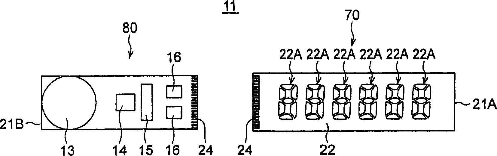
[0063] The left housing 12A and the right housing 12B are housings constituting left and right side surfaces of the arm-worn electronic device 10 , and the display unit 11 is sandwiched between the pair of left and right housings ...

no. 2 approach

[0090] The second embodiment of the present invention will be described in detail below.

[0091] In the following embodiments, a method of manufacturing a portable device (electronic device) such as the arm-worn electronic device 10 described in the first embodiment and a portable device manufactured by implementing the manufacturing method will be described.

[0092] Figure 7 It is a schematic perspective view showing the structure of a portable device manufactured by an embodiment of the method for manufacturing a portable device according to the present invention, Figure 8 is a longitudinal sectional view showing a section along the bending direction of the portable instrument, Figure 9 yes means figure 2 Cross-sectional views (a) to (e) of the respective cross-sectional structures of parts Sa to Se shown. The portable device 110 is a wearable device worn on the human body and used, and is also an electronic device having an electronic circuit built therein. More s...


PUM


Abstract

The device has a frame body ( 12 ) that has a substantial C-shape in cross section and is mounted on the body of a user, a strip-shaped display panel ( 22 ) disposed along the peripheral surface of the frame body ( 12 ), and a driver IC ( 15 ) for driving the display panel ( 22 ), wherein the display panel ( 22 ) and the driver IC are provided to different flexible substrates ( 21 A, 21 B), and the flexible substrates ( 21 A, 21 B) are disposed along the peripheral surface of the frame body ( 12 ) without being superposed on each other.

Description

technical field [0001] The present invention relates to a wearable electronic device that is worn on a user's arm and configured to display various information, a method for manufacturing a portable device, and a portable device, and particularly relates to an arm-worn portable device or a portable display device that is optimally configured The manufacturing technology of the instrument of the situation. Background technique [0002] Conventionally, arm-worn portable devices (electronic devices) such as watches and divers computers are generally known as electronic devices that are worn on the user's arm or the like and have a display unit that displays various information. Most of these arm-worn portable devices are composed of a main body having a display unit and a belt connected to the main body. The belt part is made of metal or leather, and is configured to hold the main body on the arm. [0003] On the other hand, a concept of a strap-shaped (bracelet-type) watch h...

Claims


Application Information

Patent Timeline
Patent Type & Authority Applications(China)
IPC IPC(8): G12B9/02G09F9/00G09F9/30G04G17/00G04G9/00G06F1/16
Inventor 石井润一郎荒井俊一高桥和稔
Owner SEIKO EPSON CORP
Why Eureka
Try Eureka