Geometric source preparation signal processing technique

A mixed-signal and composite-signal technology, applied in the field of signal processing, can solve problems such as crosstalk and leakage

Inactive Publication Date: 2006-09-06
THOMSON LICENSING SA
View PDF2 Cites 14 Cited by
  • Summary
  • Abstract
  • Description
  • Claims
  • Application Information

AI Technical Summary

Problems solved by technology

Absolute single-channel power guidelines have serious crosstalk or leakage issues when multiple sources are active simultaneously, especially in reverberant environments

Method used


Image

  • Geometric source preparation signal processing technique
  • Geometric source preparation signal processing technique
  • Geometric source preparation signal processing technique

Examples


Embodiment Construction

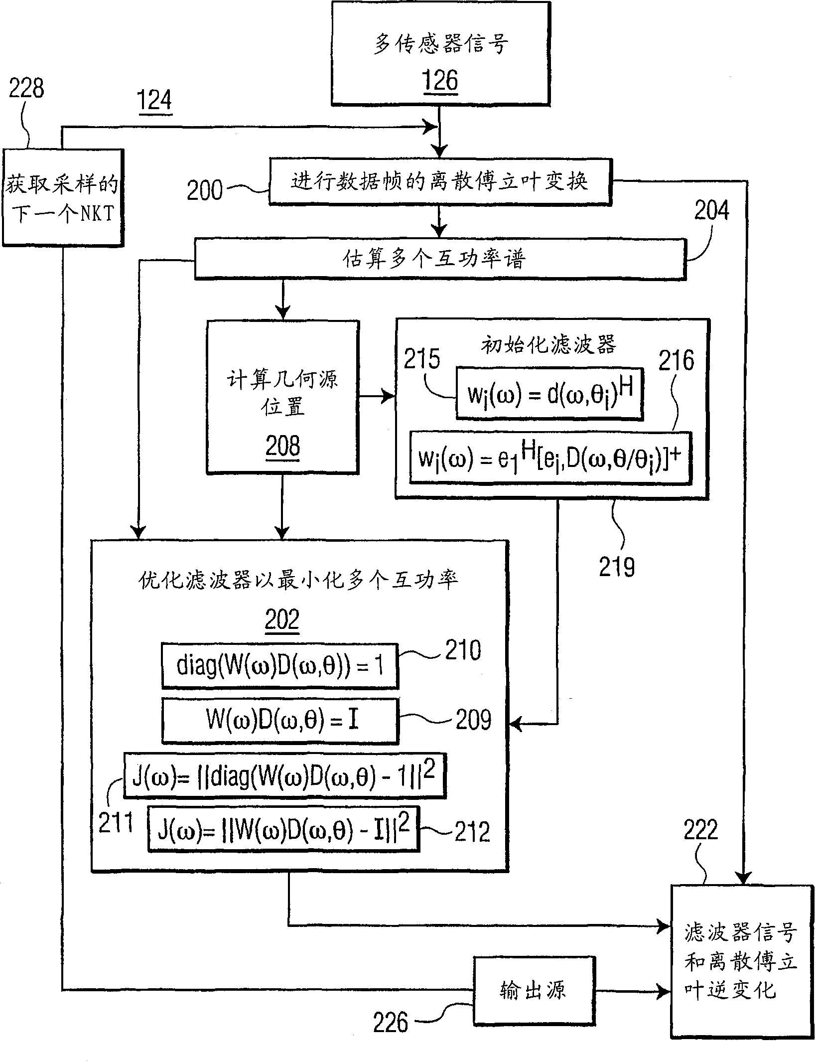
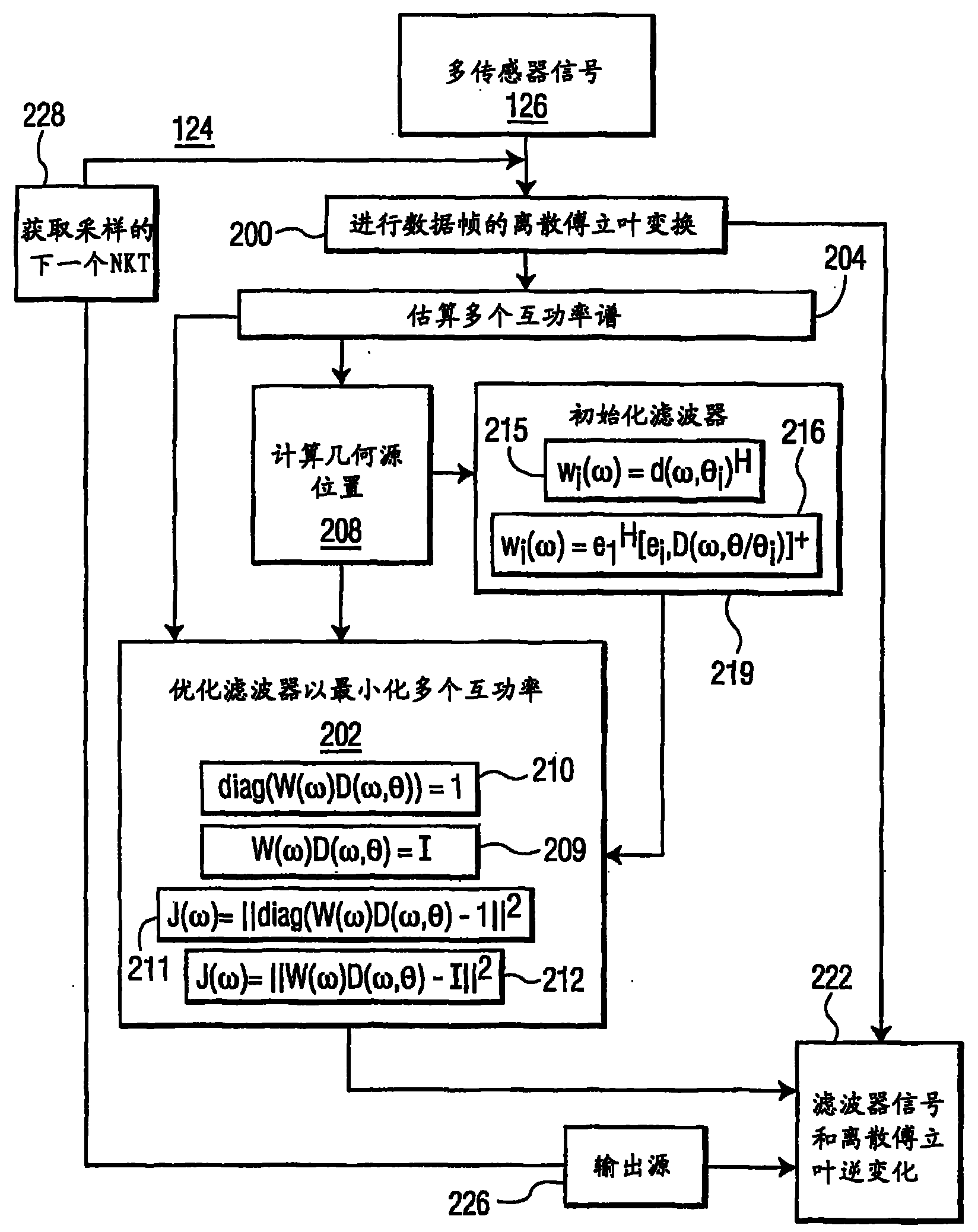
[0044] The present invention estimates the value of W(ω) obtained from known blind source separation techniques by making geometrical assumptions about the signal sources. It is assumed that the source is localized to at least the spatial resolution of the given array. The invention assumes that the signal is generated from the same location throughout the frequency spectrum and allows a geometrically enforced formulation of the filter coefficients. Different geometric enforcements are introduced, leading to a class of geometric source separation algorithms.

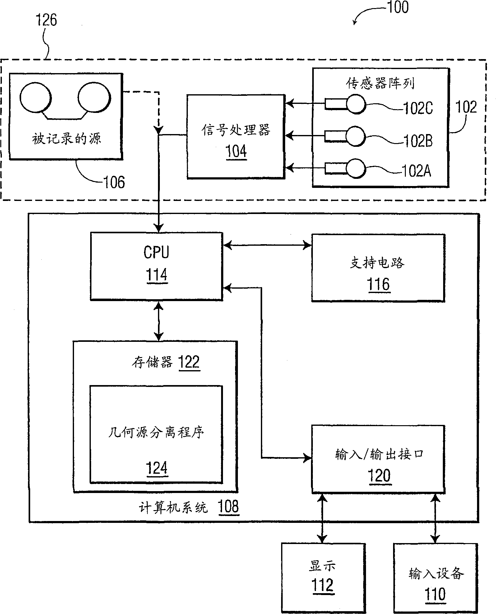
[0045] figure 1 A system 100 implementing the source separation method of the present invention is described. The system 100 includes a composite signal source 126 for providing the signal to be separated into components, and a computer system 108 for performing the geometric source separation procedure of the present invention. Source 126 may comprise any composite signal, but for purposes of illustration is shown co...


PUM


Abstract

A computer system that processes mixtures of signals, such as speech and noise sources derived from multiple simultaneous microphone recordings, in order to separate them into their underlying sources. A source separation routine optimizes a filter structure by minimizing cross powers of multiple output channels while enforcing geometric constraints on the filter response. The geometric constraints enforce desired responses for given locations of the underlying sources, based on the assumption that the sources are localized in space.

Description

technical field [0001] The present invention mainly relates to signal processing, and more particularly to a system for separating mixed signals using geometric information and adaptive beamforming techniques. Background technique [0002] Blind source separation refers to a processing method that separates a composite signal into its original component signals without prior knowledge of the characteristics of the signal. This processing method is useful in speech recognition, identification and equalization of multipath transmission (multipath) channels, signal to interference ratio (SIR, signal to interference ratio) improvement of voice recordings, monitoring applications, and hearing aid operations. [0003] In a multipath transmission environment, there is a problem in blind source separation of broadband signals, that is, there are a lot of uncertainties. Increasing the number of sensors improves performance, but leads to uncertainty in the choice of separation filter...

Claims


Application Information

Patent Timeline
Patent Type & Authority Applications(China)
IPC IPC(8): G10L21/02G01S5/18G01S3/82G06K9/62G10L21/0272H03H21/00
CPCH03H2021/0036G06K9/624G10L2021/02166G10L21/0272H03H21/0027G06F18/2134
Inventor 卢卡斯·C·帕拉克里斯托弗·阿尔维诺克莱·D·斯彭斯克雷格·L·范考特
Owner THOMSON LICENSING SA
Why Eureka
Try Eureka